May 22 2016
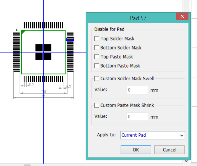
The first build failed, but for build problems. It did not make it far enough to check the design in any meaningful way. The failure was due to bridging between the pins of both MSP430s caused by an overabundance of solder. I need to review the patterns for every component in the design and shrink the size of the paste apertures, especially the 0402 parts and ICs. The final review is to carefully study the paste outlines in the gerbers themselves.
The mask shrink defaults to 0, so every new component I made has mask apertures that are far too large.
The holes for the posts should be a bit smaller, the headers flop around during assembly. A drop of Krazy Glue will hold the headers in place.
The holes for the crystal should be a bit further apart, spreading the legs to make it easier to solder in place.
The pattern for the terminal block is wrong.
I adjusted the paste apetures and ordered a new stencil. (See ). This board also failed due to bridging, but was a definite improvement over the first build.
May 28 2016
The third build succeeded as my paste application technique improved with practice and patience. I proved to myself that I can, eventually, build boards with many 0402 and 0.5mm pitch components -- but it ain't easy.
Both MSPs are operational when using the direct FET interfaces. However, the board failed functional testing due to 2 major design flaws:
Unfortunately, neither of these problems can be fixed with jumper wires. I will need to order new boards to continue. I suspect the 3.3V problem happened when DipTrace disconnected the PWR_3V net when I was reconstructing the power selectors in the schematic. I didn't notice that it had happened and failed to notice the disconnected pin in the layout.
There were a couple minor, non-fatal design flaws:
I don't see much point in ordering fixed CtrlMtr boards instead of moving on to CANMtr and continuing on that project. I will fix the CtrlMtr schematic and layout but I won't order any more CtrlMtr boards.
This is the end of the line for CtrlMtr. I declare it to be a qualified success -- I learned a lot and proved I could build the board, but it won't spin any motors.