May 4 2016
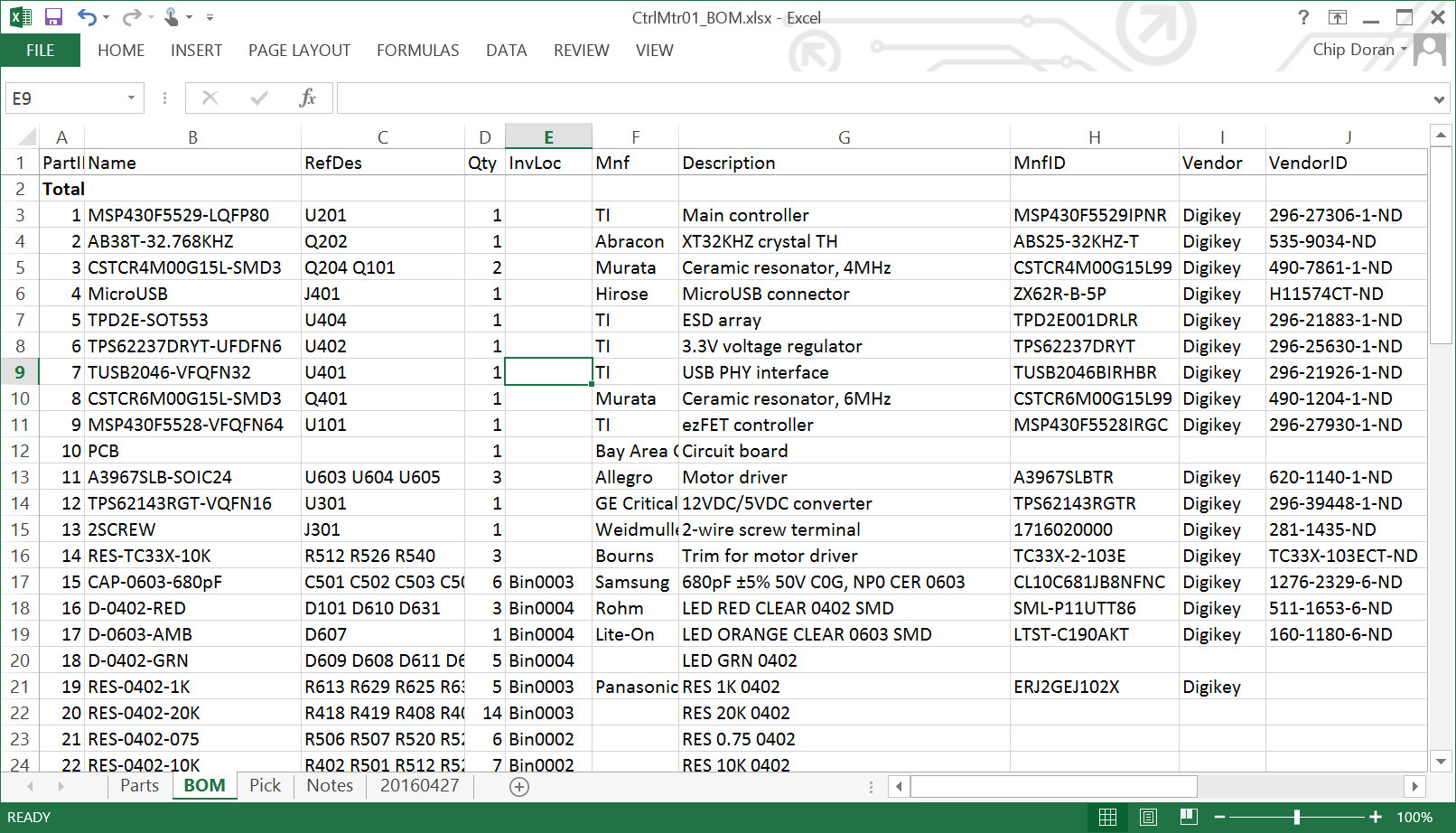
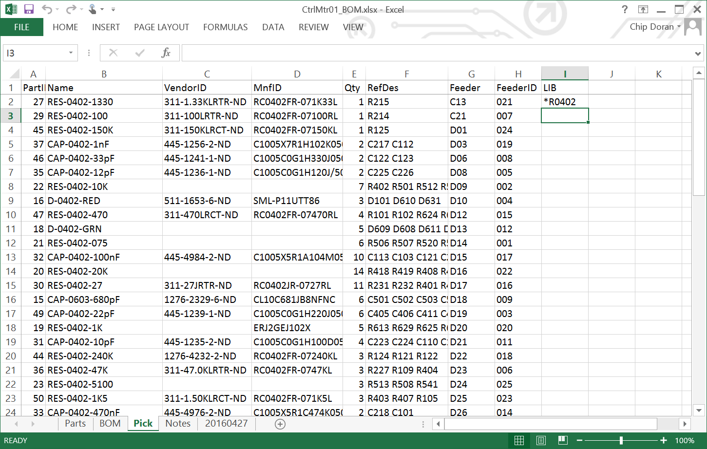
The parts have arrived, it is time to build the paper board. The first step is to load the feeders. JumpMtr serves as a starting point since the parts are still loaded. I copied the Name, RefDes, FeederID, and Feeder columns from the BOM spreadsheet to a new "Pick" sheet. The FeederID and Feeder columns only add confusion to the BOM sheet and are cut.
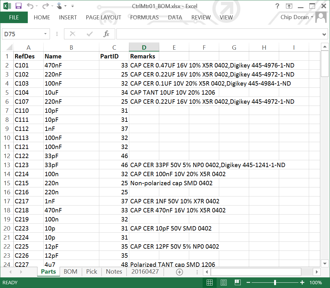
The BOM spreadsheet contains three sheets:
Whenever I make a change to the schematic that affects the BOM I need to update the schematic, Parts, BOM, and Pick sheets. I have dramatically improved BOM management with AutoBOM ()
I exported the PnP list from DipTrace and imported it into AutoTronik using UCAD, following the steps described in {THREAD_LINK:1004}. The feeders that are still occupied from the JumpMtr build were updated in the new CtrlMtr01 project.
All the new parts need to be loaded, some on autofeeders while many will be on the tray. It will be a challenge to set up all the tray parts without scattering them across the room. To minimize the time wasted digging through the parts bin, I will start with whatever part is on the top of the pile and work my way to the bottom. Paper tape works better on the tray than plastic tape; try to put the plastic tape parts in autofeeders whenever possible. I will be following the same procedure from the JumpMtr project: {THREAD_LINK:1392}
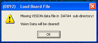
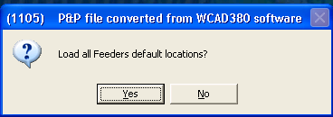
I will be modifying the Autotronik project, so I need to start up the machine. This will all be bookkeeping, so I can use a remote desktop. I want to open the CtrlMtr-Top project I created in UCAD. This is an incomplete project and Autotronik will complain a few times, just ignore the warnings. I have already assigned some feeders, choose "NO" to default locations.
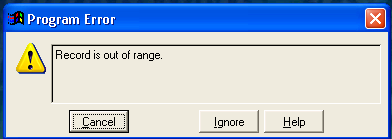
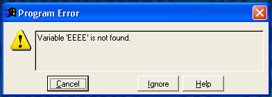
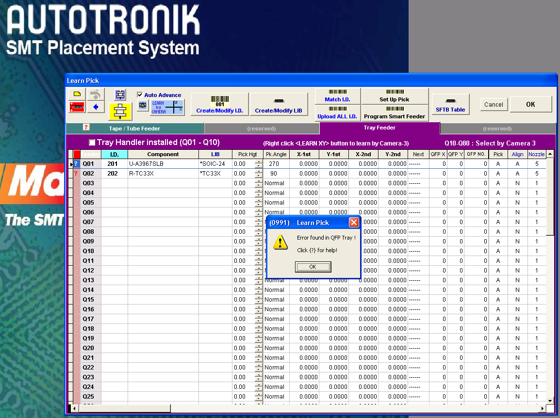
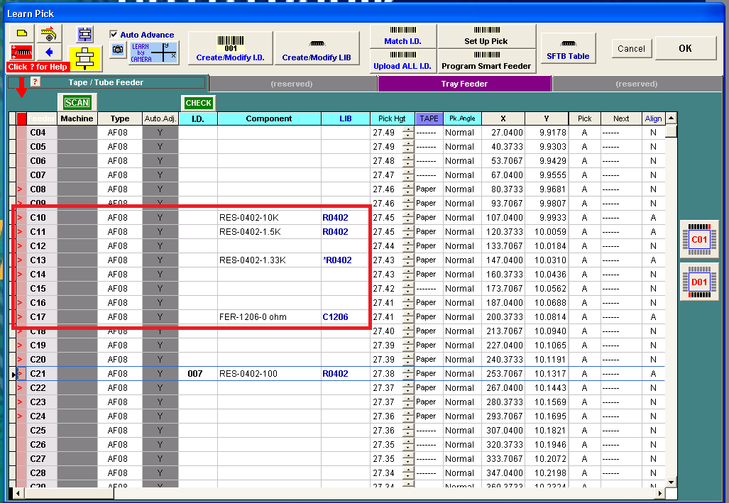
Click the "PICK" button in the toolbar to open the Learn Pick window. Autotronik will complain again because all the pick locations are zero.
I want to minimize the number of times I move the tray, as there is a significant risk of spilling parts each time. Loading the tray will be split into two phases. Phase 1 will assigning the Feeder/FeederID and mounting the parts onto the tray. Phase 2 will be creating the reference images in the machine. For this plan to work I will need to carefully label each component on the tray, otherwise I will never be able to tell one 0402 resistor from the other.
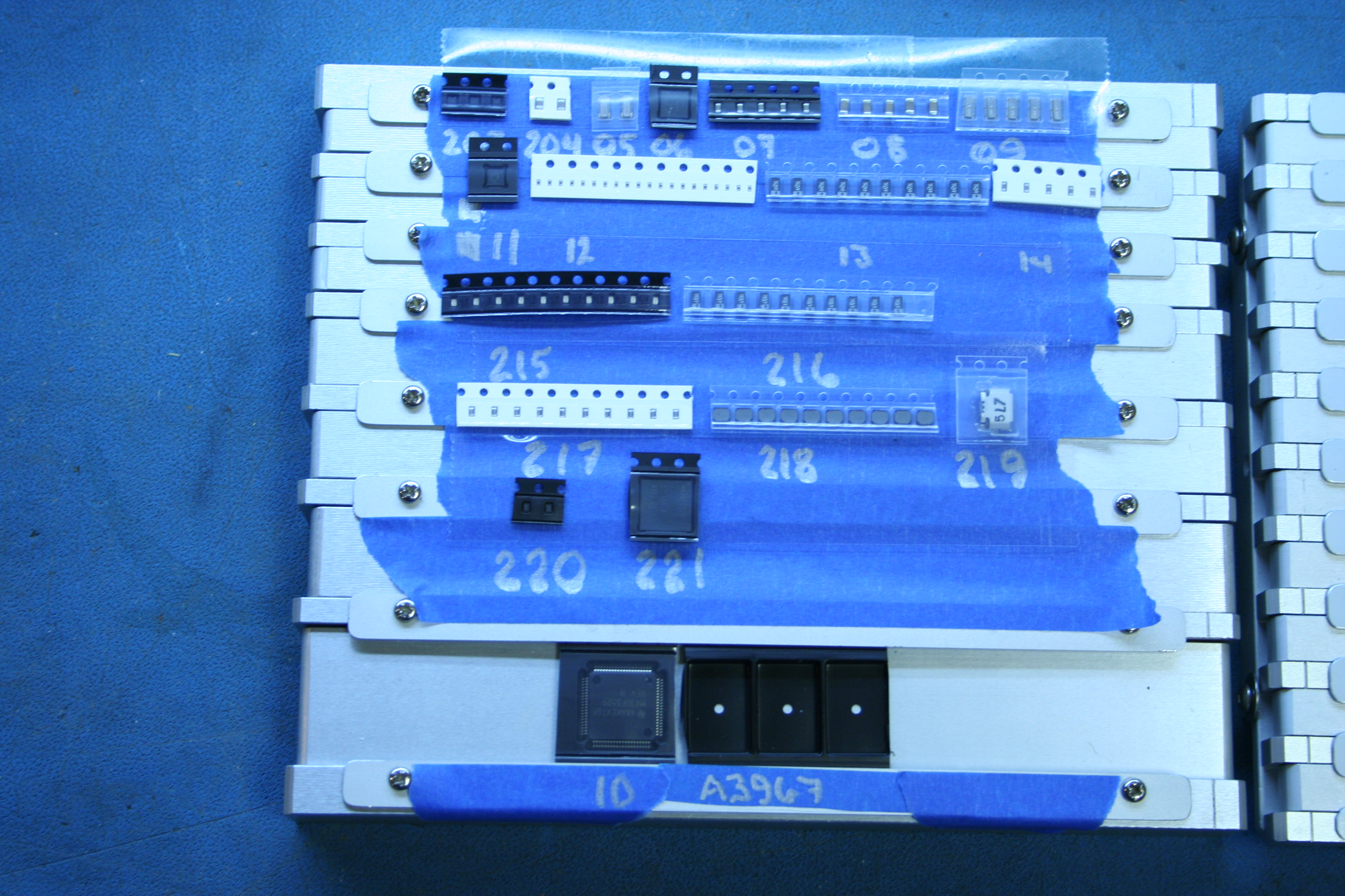
I need to prepare the tray for the cut-tape components. It is a disaster to try to secure these tiny parts using the spring-loaded channels, instead I secure the component tape to the rails using transparent double-stick tape (TDST). I start by covering most of the tray with blue painter's tape to form the workspace for the tiny components on 8mm tape. I will be filling the tray by rows, starting from the top (edge furthest away) and working down. I start each row by laying down a strip of TDST tape, leaving the blue tape over the channel exposed for writing the FeederID. The TDST needs to be laid down row by row as it is wider than the 8mm channel and will cover the area of blue tape I need to write on.
I ordered all the parts from a single vendor, Digikey. This makes the VendorID the primary key for looking up the parts in the Pick list. I sort the Pick sheet by VendorID.
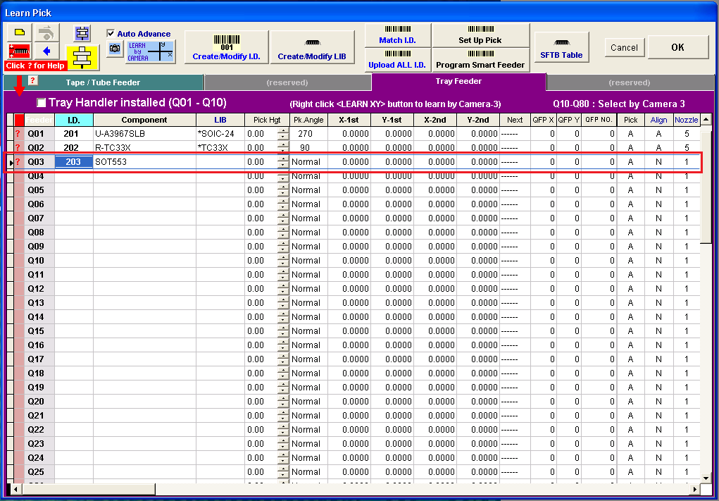
The first component out of the bin is TPD2E001DRLR (PartID 7) on a short cut tape of 10 units so it will be on the tray. UCAD assumed everything would be on tape and has already assigned it to an autofeeder location (C08), and I need to find and remove it. The next empty tray feeder is Q03 and the next unused tray FeederID (201-399) is 203. I update the Pick sheet to assign Q03/203 to PartID 7 and write the FeederID "203" on the blue tape under the space for the components.
[Image 4205]
There is only one of these per board, I slice off 3 to mount on the tray. I need to have enough tape to securely mount it, one or two units is too short. The remaining 7 go back into the bag, and in the box to be returned to the parts bin. Secure the components onto the TDST above the FeederID, sprocket holes away. Leave the cover tape in place over the components for now.
[Image 4206] [Image 4207]
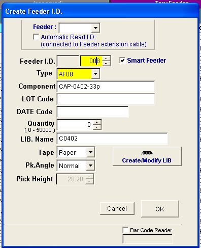
In Autotronik, click the Q03:ID cell to create a new FeederID. Set the FeederID to the next unused number from 200-399, which is 203. The component is a SOT553, which is conveniently part of my component name in the Pick list. This is a new component shape and will require creating a reference image, so leave LIB, pick angle, and pick height blank for now.
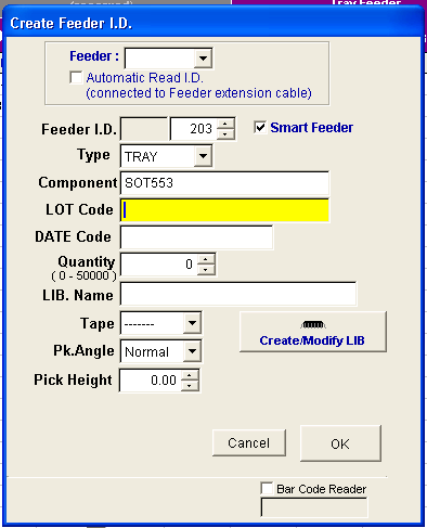
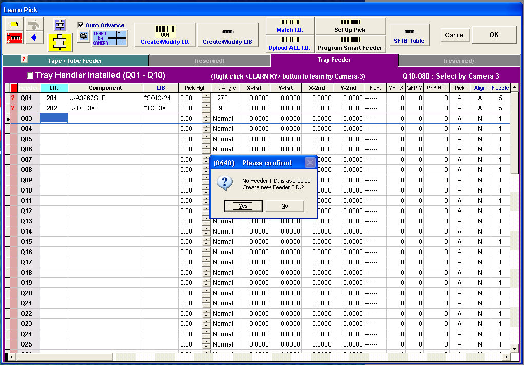
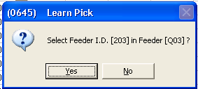
Click OK to close the FeederID window, and Yes to assign the FeederID to the Feeder. Autotronik will complain because there is no LIB assigned to the feeder, I will do that in Phase 2.
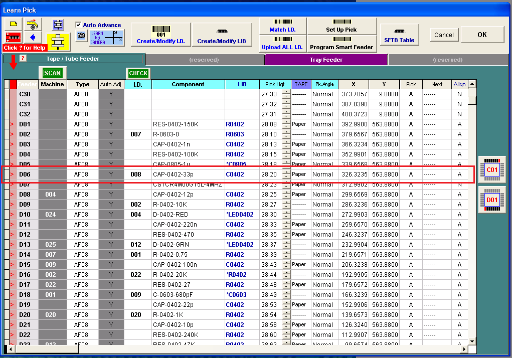
The next component out of the box is C1005C0G1H330J050BA, also known as 445-1241-1-ND, CAP-0402-33pF, or PartID 46. This is a cut tape of 1000 units, which is long enough to run through an autofeeder. I grab an empty autofeeder and write the FeederID "008" down in the Pick sheet. The tape is too short to require a reel and I can skip mounting a reel holder. I will be running the bare tape through the feeder. Because UCAD has already decided the optimal location for all the autofeeders, I need to find the component (by name "CAP-0402-33p") in the tape feeder list (D06), create the FeederID (008), and mount the autofeeder at the proper location (D06) on the machine.
I remove the components from the vendor bag, write the Feeder location on the label (in pencil) to make my life easier when unloading later, and feed the tape through the autofeeder. There is a problem with running cut tape through an autofeeder: I need at least 250mm of cover tape to run from from where the autofeeder peels the cover back to the tension spool. This is necessary, otherwise the cover tape binds up under the pick cover and jams the feeder. With a component every 3mm this will waste 83 components of the 1000 available. The cost ($0.91) is not the problem, wasting 8.3% of my stock is the problem. I wish I had a spool of the yellow leader tape that Digikey uses for its Digi-Reels but Digikey doesn't sell it. It is nothing more than 8mm mylar tape. I wonder if I could use thread? See SpliceRite.com.
Making this even more irksome, I can't advance the tape without mounting the autofeeder in the machine, and I can't use the staging area since it only runs in reverse. I need to use Feeder D31 and let the wasted components fall into the area under the autofeeders. Use D31, not D32, to minimize the number of components that bounce onto the floor. Pull the cover tape back to the spool while advancing the component tape using the button on the autofeeder. Pull firmly enough to prevent the tape from binding under the pick cover, but not hard enough to break the tape. Secure the cover tape in the tension spool. Once the cover tape is secure, remove the autofeeder from D31 and move it to its production slot (D06).
[Image 4208] [Image 4209] [Image 4210] [Image 4211] [Image 4212] [Image 4213]
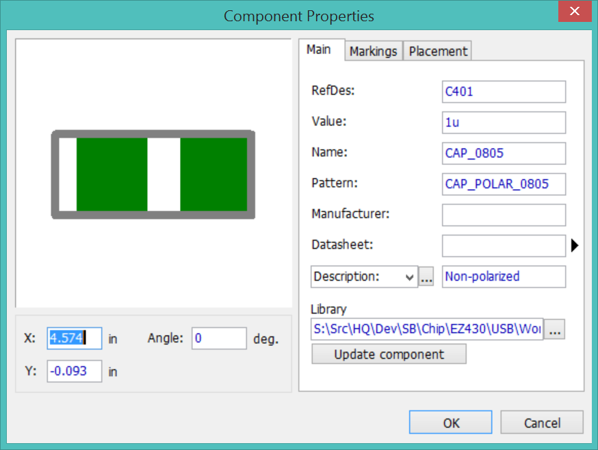
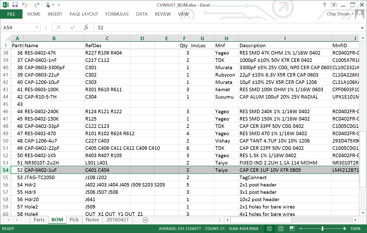
The next component out of the box is 587-1284-1-ND, LMK212B7105KD-T, CAP CER 1UF 10V X7R 0805, PartID 52, 2 parts per board. This is a SMT/0805 on cut tape, quantity 100, and a part pitch of 4mm. If I use an autofeeder the waste (250/4= 62) will be 62%. This will be another tray part. The tape is paper (cardboard) which will make it easier to secure to the tray and I only need to mount 2 parts. I remove the component from the tape feeder (D05), noting that the Autotronik component name is "CAP-0805-1u". I create a new tray feeder Q04/204 for the component using the UCAD name.
I noticed that the actual part is a SMT/0805 while my BOM lists it as "CAP-0402-1uF", something is wrong. I need to go back to the layout to make sure the size is correct for C401 and C404. The size is correct in the layout and the schematic, and it appears to be just a typo in the BOM. I correct the name to "CAP-0805-1uF" in both the BOM and Pick sheets.
I write the FeederID "204" on the tray and mount the tape containing the 2 parts.
Next is 490-7861-1-ND, CSTCR4M00G15L99-R0, CER RES 4MHZ 39PF SMD, PartID 3, 2 parts (Q204,Q101), plastic cut tape with 4mm pitch. This will be another tray pick. I remove "CSTCR4M00G15L-4MHZ" from tape feeder D07 and create tray feeder Q05/205. I trim off 2 components from the component tape and mount it on the tray.
Next is 296-21926-1-ND, TUSB2046B1RHBR, IC 4-PORT HUB FOR USB 32-QFN, PartID 7, 1 parts (U401), Qty 5 on plastic tape with 8mm pitch. This will be a tray pick. I remove "TUSB2046B-TUSB2046BIR" from Tape feeder C18 and create tray feeder Q06/206. I trim off 1 component from the tape and mount it on the tray.
1276-2867-1-ND, CL10A226KQ8NRNE, CAP CER 22UF 6.3V XSR 0603, PartID 39, 1 part (C302), Qty 100 on plastic tape with 4mm pitch. Tray. I remove "CAP-0603-22uF/6V" from tape feeder C12 and create tray feeder Q07/207.

At this point I realized that if I populate the tray with only enough parts for a single board, I would be forced to restock the tray after every build attempt. Ugh! Except for a few ICs, the cost of a few parts is not the primary expense. The dollar cost is overwhelmed by the time required. I should be stocking the tray with enough parts to build 5 boards. Hopefully this will be enough to complete one, and I will go through the exercise of stocking the tray only once.
The expensive parts (USB hub, MSP430's, etc.) will be stocked with only enough parts for a single board. The extra inconvenience is mitigated by the larger size of these components that makes it easier to restock them.
I trim off 5 #39 components and mount them.
1276-1075-1-ND, CL31A106KAHNNNE, CAP CER 10UF 25V X5R 1206, CAP-1206-10uF, #40, 1 part (C303), Qty 100 on plastic tape 4mm pitch. Move "CAP-1206-10uF/30V" from tape feeder C16 to tray feeder Q08/208. Mount 5 components.
445-1256-1-ND, C1005X7R1H102K050BA, CAP CER 1000PF 50V X7R 0402, #37, CAP-0402-1nF, 2 parts (C217,C112), Qty 1000 on paper tape with 2mm pitch. Autofeeder waste will be (250/2= 125) 12.5%. These parts are both tiny and cheap, this will be a direct autofeeder in D03/019.
445-1235-1-ND, C1005C0G1H100D050BA, CAP CER 10PF 50V C0G 0402, #31, CAP-0402-10pF, 4 parts (C223,C224,C110,C111), Qty 1000 on paper tape with 2mm pitch. Autofeeder waste will be 12.5%. Tiny, cheap, and I need to place a lot of them, this will be a direct autofeeder in D21/011.
445-1236-1-ND, C1005C0G1H120J050BA, CAP CER 12PF 50V C0G 0402, #35, CAP-0402-12pF, 2 parts (C225,226), Qty 1000 on paper tape with 2mm pitch. Direct autofeeder D08/005.
D08 is already occupied by FeederID 004. The pick sheet from the JumpMtr project tells me this is "D-0402-RED", which has been reassigned to D10. D10 is occupied by FeederID 024 "D-0603-AMB", which has been reassigned to C15, which is empty. I rearrange the feeders and update the CtrlMtr pick sheet.
I should have rearranged the JumpMtr feeders before loading any new feeders. It is much more confusing now that there is a mix of new and old feeders.
I need to stop loading new feeders and rearrange the old feeders. I need to stand in front of the machine and for every feeder slot that contains an autofeeder, check the FeederID against the Autotronik configuration. If it does not match, move the autofeeder. This task did not take very long, about 10 minutes.
718-1118-1-ND, 293D106X0010A2TE3, CAP TANT 10UF 10V 20% 1206, #34, CAP-1206-10uF, 2 parts (C230, C104), Qty 1000 on plastic tape with 4mm pitch. Direct autofeeder D28/006 "CAP-POLAR-1206-10u".
490-1204-1-ND, CSTCR6M00G53-R0, CER RES 6MHZ 15PF SMD, #8, "CSTCR6M00G15L-SMD3", 1 part (Q401), Qty 10 on plastic tape 4mm pitch. Move "CSTCR6M00G15L-6MHZ" from C14 to Q09/209. I mount 5 parts on the tray.
296-27306-1-ND, MSP430F5529IPNR, IC MCU 16BIT 128KB FLASH 80LQFP, #1, MSP430F5529-LQFP80, 1 part (U201), Qty 5 on plastic tape with 20mm pitch. Move "MSP430F5529-LQFP80" from C23 to Q10/210. I mount 1 part on the tray.
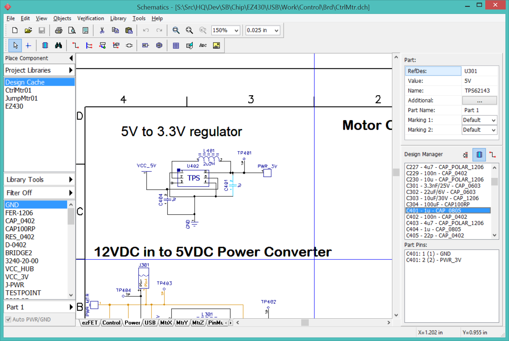
296-39448-1-ND, TPS62143RGTR, IC REG BUCK 5V 2A SYNC 16QFN, #12, TPS62143RGT-VQFN16, 1 part (U301), Qty 10 on plastic tape with 8mm pitch. Move "TPS62143-5V" from tape C10 to tray Q11/211. Mount 1 part.
1276-2275-1-ND, CL10C332JA8NNNC, CAP CER 3300PF 25V NP0 0603, #38, CAP-0603-3300pF, 1 part (C301), Qty 1000 on paper tape with 4mm pitch. "CAP-0603-3.3nF/25V" on autofeeder C20/015.
445-4972-1-ND, C1005X5R1C224K050B8, CAP CER 0.22UF 16V X5R 0402, #25, cap-0402-220nF, 4 parts (C215,C216,C102,C107), Qty 40 on paper tape with 2mm pitch. Move "CAP-0402-220n" from tape D11 to tray Q12/212. Mount 20.
718-1146-1-ND, 293D475X9010A2TE3, CAP TANT 4.7UF 10V 10% 1206, #48, CAP-1206-4u7, 2 parts (C227, C403), Qty 10 on plastic tape with 4mm pitch. Move "CAP-POLAR-1206-4u7" from tape D29 to tray Q13/213. Mount 10.
445-4976-1-ND, C1005X5R1C474K0508C, CAP CER 0.47UF 16V X5R 0402, #33, "CAP-0402-470nF", 2 parts (C218,C101), Qty 1000 on paper tape with 2mm pitch. Autofeeder D26/014.
I have only 8 autofeeders remaining, I need to reserve them for components that are on reels or at least 1000 pieces. There are 12 more such components, so I will need to bump 4 components off the autofeeders.
The bumped components will be those with 2 or fewer parts, preferably 0603 or larger:
I pull C20/015, wasting 320mm or 80/1000 components.
I pull C15/024. I didn't waste any components and I tried to salvage the cover tape by cutting a strip of Scotch tape to fit.
I have been working on this for about 6 hours and I am a bit over halfway. Documenting the entire tedious process has slowed it down considerably, and I made a couple mistakes that wasted some time. I expect that with practice this could have been done in about 4 hours. A team of 2 people, one to do the data entry and bookkeeping and the other to load the parts, could have made it this far in about two or three hours.
An infinite supply of autofeeders would reduce the time a great deal. I would load the feeder once and not unload it until the parts ran out.
May 6 2016
Loading the feeders, day 2.
587-1638-1-ND, NR3010T2R2M, FIXED IND 2.2UH 1.1A 114 MOHM, #51, "NR3010T-2u2H", 2 parts (L301,L401), Qty 10 on plastic tape 4mm pitch. Move "NR3010T-2u2H" from tape D30 to tray Q18/218.
H11574CT-ND, ZX62R-B-5P, CONN RCPT MICRO USB B SMD R/A, #4, "MicroUSB", 1 part (J401), Qty 10 on plastic tape 12mm pitch. Move "MicroUSB-" from tape C09 to tray Q19/219. I will mount only a single piece since this is a big and expensive part.
296-25630-1-ND, TPS62237DRYT, IC REG BUCK 3.3V 0.5A SYNC 6SON, #6, "TPS62237DRYT-UFDFN6", 1 part (U402), Qty 10 on plastic tape 4mm pitch. Move "TPS62237-" from tape C24 to tray Q20/220. I mount 2 pieces.
296-27930-1-ND, MSP430F5528IRGCR, IC MCU 16BIT 128KB FLASH 64VQFN, #9, "MSP430F5528-VFQFN64", 1 part (U101), Qty 5 on plastic tape 12mm pitch. Move "MSP430F5528-MSP430F5528" from tape C22 to tray Q21/221. This is a big and expensive part so I mount a single piece.
311-470LRTR-ND, RC0402FR-07470RL, RES SMD 470 OHM 1% 1/16W 0402, #47, "RES-0402-470", 4 parts, Qty 10000 on paper tape 2mm pitch. I mount the reel on tape feeder D12/015.
311-150KLRTR-ND, RC0402FR-07150KL, RES SMD 150K OHM 1% 1/16W 0402, #45, "RES-0402-150K", 1 part, Qty 10000 on paper tape 2mm pitch. I mount the reel on tape feeder D01/024.
311-100LRTR-ND, RC0402FR-07100RL, RES SMD 100 OHM 1% 1/16W 0402, #29, "RES-0402-100", 1 part, Qty 10000 on paper tape 2mm pitch. I mount the reel on tape feeder C21/007.
445-4984-2-ND, C1005X5R1A104M050BA, CAP CER 0.1UF 10V X5R 0402, #32, "CAP-0402-100nF", 10 parts, Qty 10000 on paper tape 2mm pitch. I mount the reel on tape feeder D15/017.
12:12> 311-1.50KLRTR-ND, RC0402FR-071K5L, RES SMD 1.5K OHM 1% 1/16W 0402, #50, "RES-0402-1K5", 3 parts, Qty 10000 on paper tape 2mm pitch. I mount the reel on tape feeder D25/023. Completed loading 12:28 in 16 minutes.
311-1.33KLRTR-ND, RC0402FR-071K33L, RES SMD 1.33K OHM 1% 1/16W 0402, #27, "RES-0402-1330", 1 part, Qty 10000 on paper tape 2mm pitch. I mount the reel on tape feeder C13/021. (7:22 minutes to load)
311-1.00MLRTR-ND, RC0402FR-071ML, RES SMD 1M OHM 1% 1/16W 0402, #28, "RES-0402-1M", 2 parts, Qty 10000 on paper tape 2mm pitch. I mount the reel on tape feeder D27/013. (7:25)
1276-4232-2-ND, RC1005F244CS, RES SMD 240K OHM 1% 1/16W 0402, #44, "RES-0402-240K", 3 parts, Qty 10000 on paper tape 2mm pitch. I mount the reel on tape feeder D22/018. (6:52)
311-27JRTR-ND, RC0402JR-0727RL, RES SMD 27 OHM 5% 1/16W 0402, #30, RES-0402-27, 11 parts, Qty 10000 on paper tape 2mm pitch. I mount the reel on tape feeder D17/016. (5:39)
A102199TR-ND, CPF0603F100KC1, RES SMD 100K OHM 1% 1/16W 0603, #41, RES-0603-100K, 3 parts, Qty 1000 on paper tape. I mount the reel on tape feeder D28/010. (9:29)
311-47.0KLRTR-ND, RC0402FR-0747KL, RES SMD 47K OHM 1% 1/16W 0402, #36, RES-0402-47K, 3 parts, Qty 10000 on paper tape 2mm pitch. I mount the reel on tape feeder D23/006. (6:01)
445-1239-1-ND, C1005C0G1H220J050BA, CAP CER 22PF 50V C0G 0402, #49, CAP-0402-22pF, 6 parts, Qty 1000 on paper tape. I mount the bare tape on autofeeder D19/003. (9:28)
13:30> Done.
There is no need for the expensive machined tray platform with the spring-loaded channels. In fact, it causes more problems than it solves and a perfectly acceptable replacement would be a simple flat surface. The PnP head won't descend all the way to the work area deck, so a replacement would need to be close to the same height. The top surface should have a grid to make it easy to align the tape and parts. It would need something to prevent it from moving around, either weight or non-slip pads.
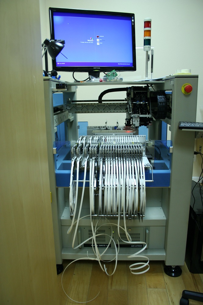
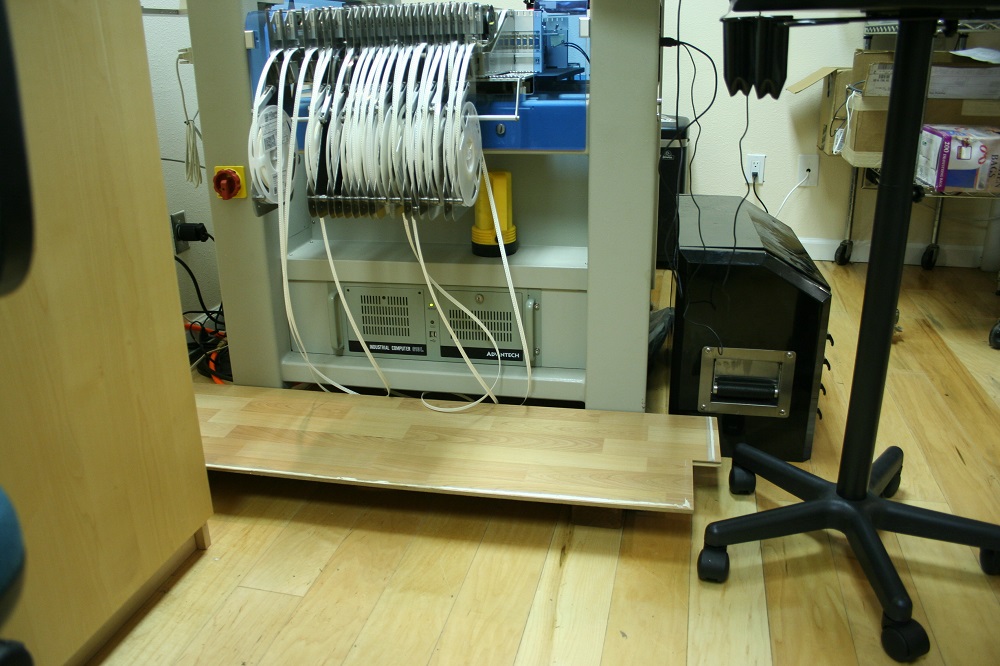
I need to work directly on the machine to use the vision system and I need to be careful not to step on the bare tape that dangles under the feeders and spools on the floor. After stepping on the dangling tape a second time, I rigged up a guard to prevent crushing the tape while I worked on the machine. It has worked quite well, I need to build a more permanent version.
With all the parts loaded, I need to train the machine to pick and recognize each component. I will be picking and replacing the tray components, so I need to record the original orientation of the part on the tray. Everything is in its original tape with the sprockets away, and the orientation can be found in the device datasheet.
I open the Pick window and work my way down the component list. It helps to sort the Pick sheet by Feeder.
I can let the machine scan all the smart feeders.
If there are any feeders without a FeederID, they are left over from the previous project and should be deleted.
As I work my way down the list in Autotronik, I record the final component LIB name in the Pick sheet. This will be useful both for future reference and as a cross-check to make sure all the components from the BOM have been loaded.
The most efficient procedure for many feeders is to first set all the pick locations (Learn by Camera). Then determine the pick height for the first component and apply this height to all the other components. Finally, perform the Verify Pick operation on all the components, tweaking the pick height (generally moving it 0.20mm lower) for parts that don't pick properly.
Turn OFF "Auto Advance". For each component in the tape feeder list:
I started the process of setting the pick configuration at 17:30. I finished setting the locations at 18:20. I finished the Verify Pick for all the autofeeders at 18:55.
The autofeeder components are ready. The tray components have been mounted and entered into the pick table, and it is time to set the pick locations and heights. This means removing the cover tape from the tray components, which means I need to be very careful when handling the tray from now on!
All the tray components are positioned on the tray with the sprocket holes away, rotated 90° clockwise compared to a normal tape feeder pick. In Autotronik terms, this is a Pk Angle of 270.
I want to consume the tray items from right to left to minimize travel to the board. UPDATE: This makes setting the pick locations much more tedious. It might be better to move the tray to the right side of the work area, and consume the parts from left to right.
Set the QFP-X (count of pieces per row), QFP-Y (number of rows), and QFP-No (index of first piece to pick) values before setting the pick locations. Usually, including this case, QFP-Y and QFP-No are all set to 1, and QFP-X is set to the number of pieces on the tray.
I finished setting the pick locations for the tray components at 20:00. I will set the LIB and Pk Hgt tomorrow.
==[]==
May 7 2016
Loading the Autofeeders, Day 3.
I cross-checked the PnP pick table against the pick sheet. Part #34 was assigned the wrong feeder in the pick sheet.
Why are parts #34 and #40 2 different 1206 10uF caps? #34 is a 10V tantalum cap, #40 is a 25V ceramic. Tantalum caps hold more charge than ceramics and are used for power lines. Tantalum caps are polarized and must be placed in the correct orientation. Ceramic caps can be placed in either orientation. I need to check the PnP LIB to make sure #34 is marked as polarized. (And then double-check the other caps.)
TODO: The PnP name for polarized (TANT) caps needs to include an indicator that it is polarized and the voltage rating. #34 "CAP-1206-10uF" should be renamed to "C1206+-10uF/10V". (Or something like that.) Adding the '+' to the NAME lets me know which LIB to use. This would be transformed to "C1206+-10uF%10V" while importing from DipTrace to UCAD.
I need to review the caps before continuing. Starting with the schematic, I need to suffix the valus for the polarized caps with a '+' character, make sure the proper pattern is being used, update the component name in the BOM sheets, update the names in the PnP tables.
Fortunately, I had the foresight to make sure I used the proper schematic symbol for the polarized caps. This lets me quickly click through the component list of the Design Manager and look at the symbol. If it is a polarized cap, I add a '+' to the value field. I had used the notation of "CAP_POLAR_1206", I want to change this to "C1206+" and "10uF/10V". The BOM sheets (Part, BOM, Pick) need to be updated. If I update the names in the PnP pick tables, I need to also make the change to the PnP place table.
I filled in the LIB definitions for the standard parts (caps and resistors) on the tray. There are a number of custom component LIB definitions that need to be created.
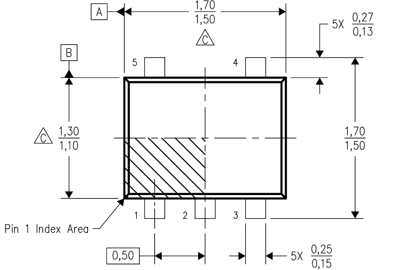
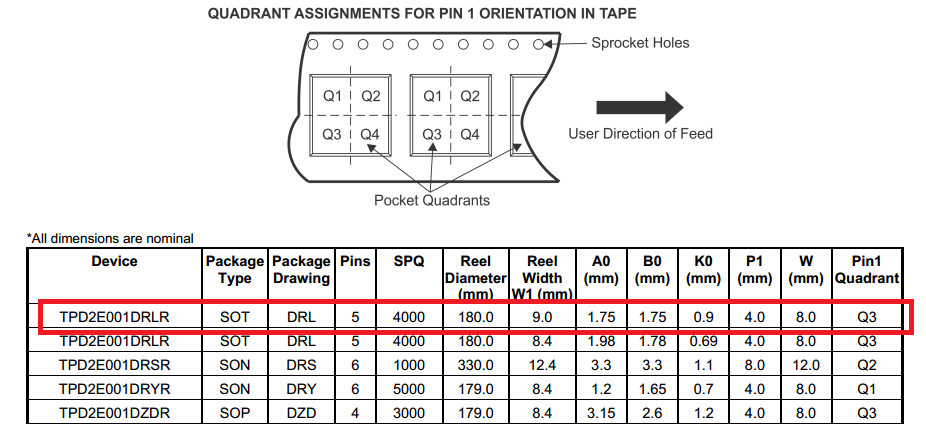
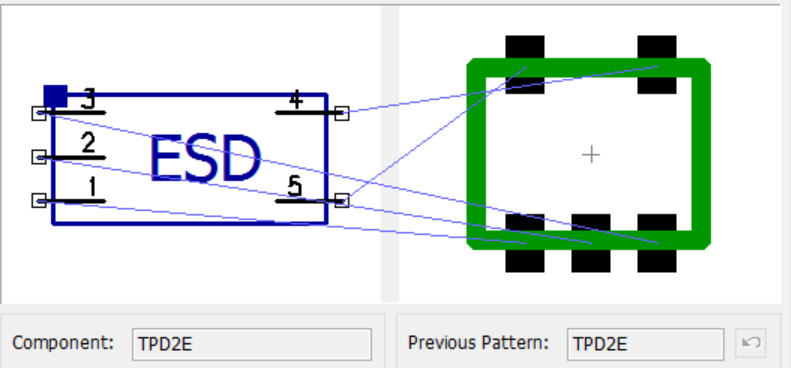
Q03/203, SOT553, #5 TPD2E001DRLR. I created "*SOT553".
I am again confounded by the pick angle. Starting from the datasheet, TPD2E001DRLR is oriented in the tape (with the sprocket holes on the top) with pin 1 in Q3 (lower left). The pick orientation needs to be reconciled with the schematic pattern. When the part is on the nozzle to define the reference image, it needs to be oriented to match the DipTrace component pattern. In this case, this means the two pins pointing UP. Setting the pick angle to NORMAL produces the proper orientation on the nozzle. (This is a bit surprising, it may be that Autotronik assumes "normal" on the tray is sprocket on top, while "normal" on the tape is sprocket on the left.)
This project uses 25 autofeeders and 23 tray locations.
It took me most of four days to load the parts, configure the machine, and validate everything. I spent a lot of time documenting and photographing every tiny detail and I am still learning exactly what the PnP software expects. I believe a reasonable expectation for a speed run on this project would be about a day for a solo operator; if I started at 9am I would expect to have performed a complete, non-stop production run by 6pm. If I were extremely well organized and the spreadsheets were in perfect order, just loading the machine could be trimmed down to half a day.
It takes a minimum of 6 minutes to load a feeder, with autofeeders and tray mounts taking roughly the same time. With 48 components to load, there is a floor of almost five man-hours just to physically load the parts.
An assistant to read off the numbers, help with the data entry, and load some parts would cut the time dramatically and might get it down to 2-4 hours.