

May 7 2016
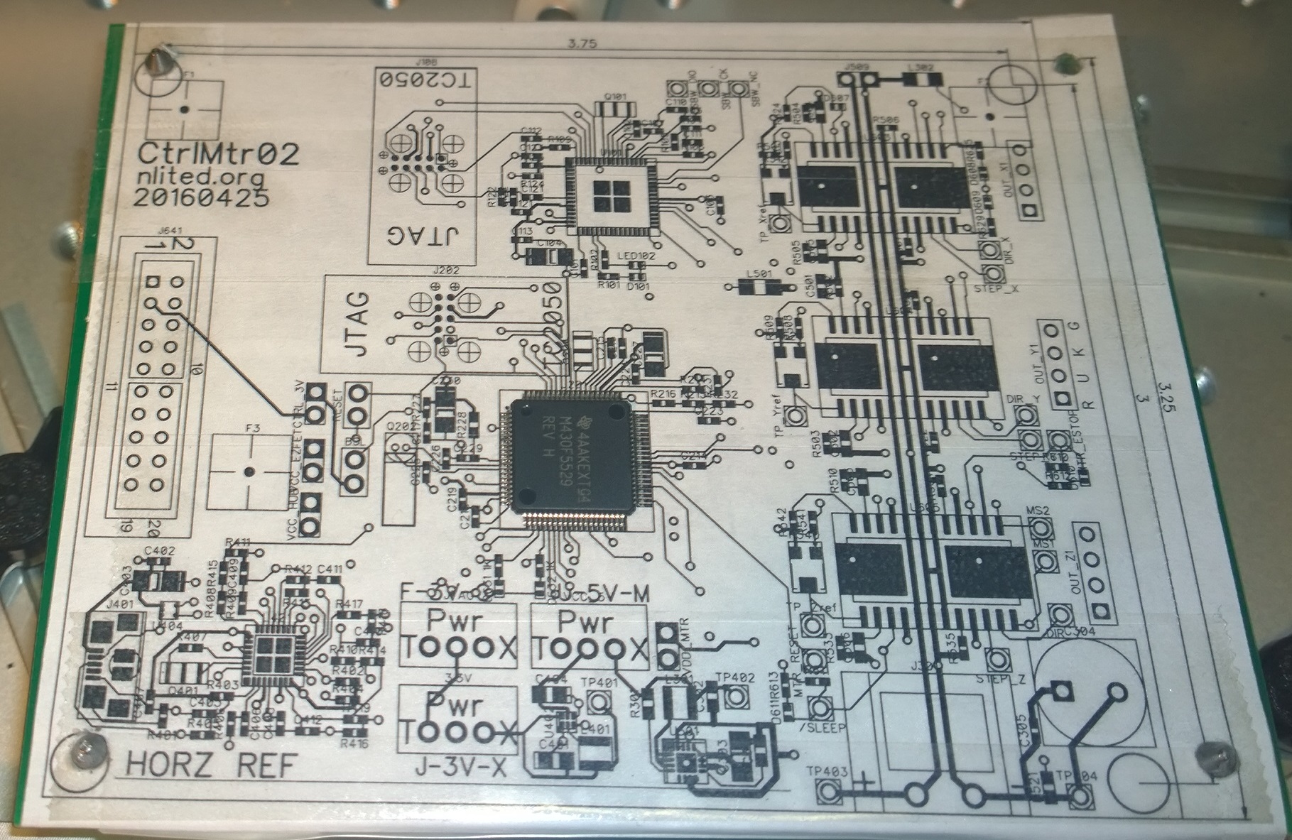
The proof will be placing the part on the paper board and checking the final orientation. I need to prepare a paper board: print the layout on paper, mount it to some scrap PCB, apply TDST.
I didn't have a PCB that was large enough so I glued three smaller boards together. This worked well except that it no didn't fit into the pneumatic clamp because of the second ply on the bottom. I should have offset the bottom board to give clearance on the away/top edge. The underhang on the close/bottom edge would not interfere with anything.
Instead, I found another adjustable support pin in the PnP spares kit. The board is supported by 3 pins and an oddball support with a bull-nose that doesn't fit in the mounting hole but is shorter. Not ideal, but good enough for this.
The TPD2E part is too tiny. I need to continue this experiment using the MSP430F5529 and A3967, which are the largest components on the board.
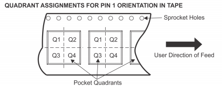
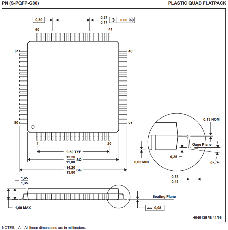
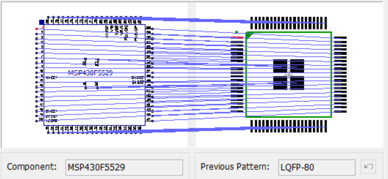
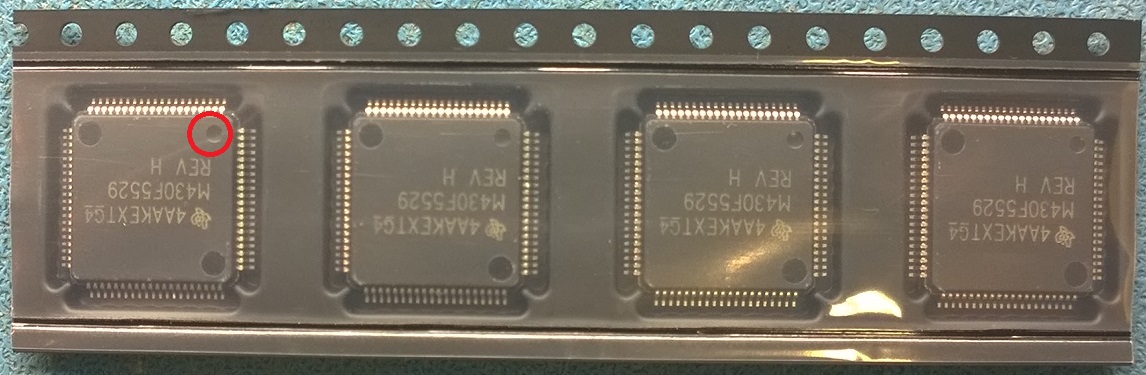
The MSP430F5529 is packaged with pin 1 in the upper right (sprocket away/up). The component pattern has pin 1 in the upper left. To translate pin 1 from the pattern (upper left) to the pick (upper right) is a counter-clockwise rotation of 270°. The pick angle is 270.
NOTE: The marking text on the component is very misleading! It is inverted (upside-down) when in the tape (with pin 1 upper right), and sideways (reading bottom to top) when placed on the board (with pin 1 upper left). Do not be misled! Look only at the pin 1 marking, which itself is misleading since it is the smaller of the three dots.
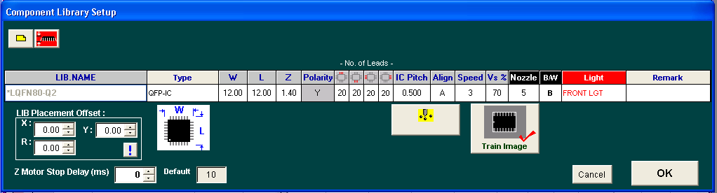
I create a new PnP component LIB named "LQFP80-Q2". Width=12mm, Length=12mm, Height=1.40mm.
A practice production run is created by clicking "Skip All" in the Learn Place window and unchecking (this means do place) only U201 - MSP430F5529.
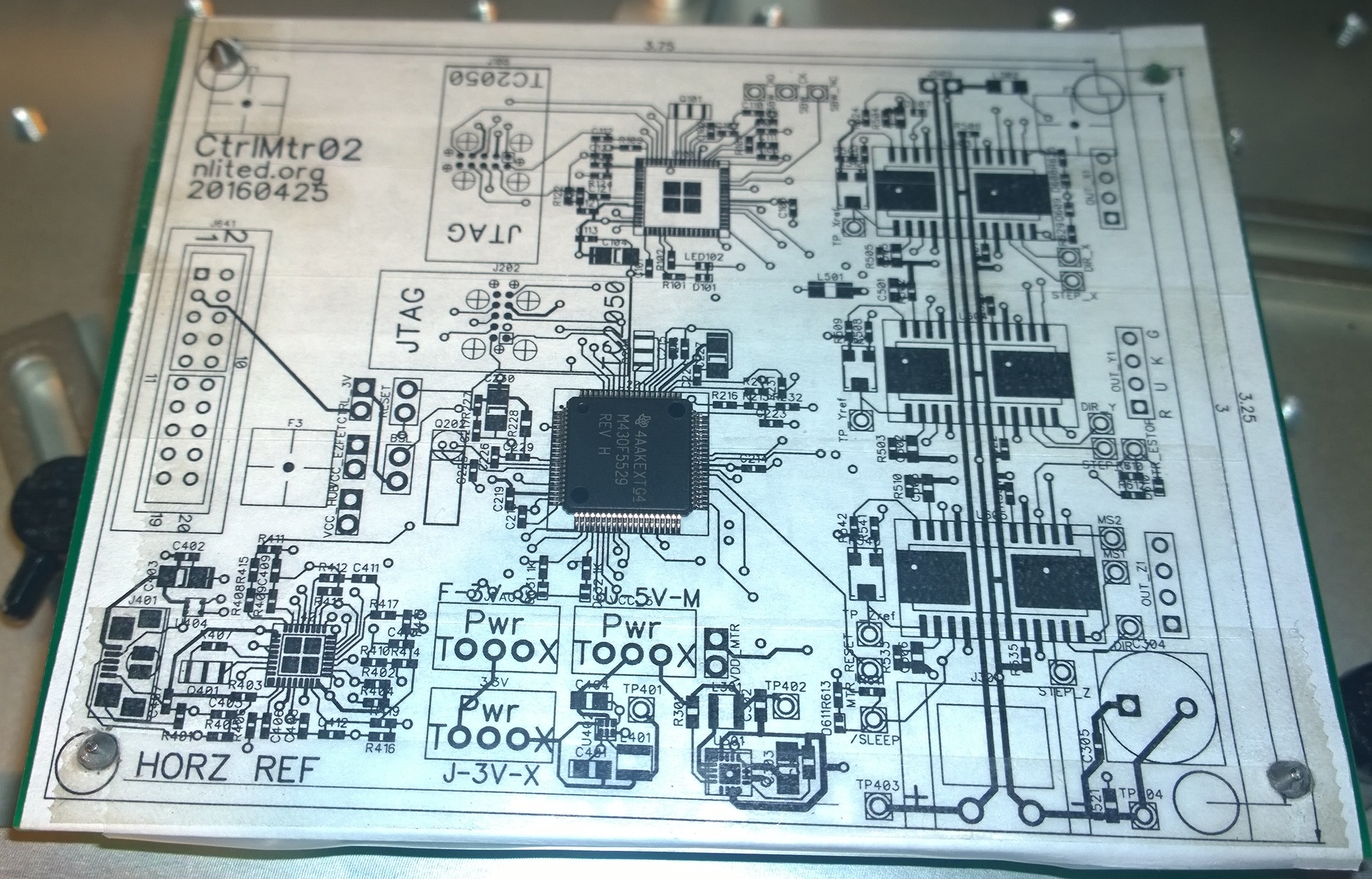
Final result: The placed component is oriented properly.

In the schematic drawing of the components, pin 1 is typically located in the upper left corner of the part. It appears that with quad parts (QFP, QFN) pin 1 is typically located in the bottom left corner. I would probably avoid a lot of confusion and mistakes in the future by changing my patterns to conform.
Pin 1 goes in the bottom left corner of QFP and QFN parts.
Now I need to tweak the pick offsets to center the pins on the pads. I simulate a bad pick by moving the pick location away from the center of the part, but still close enough to pick it up.
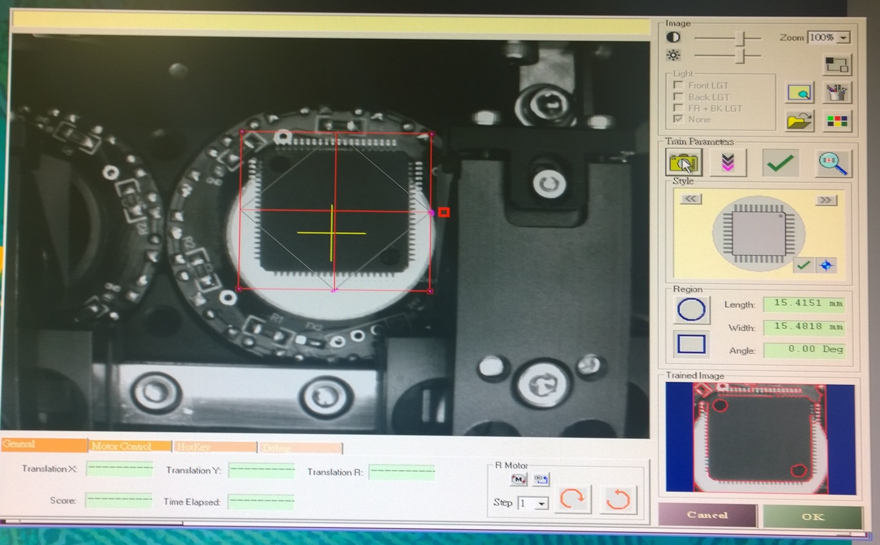
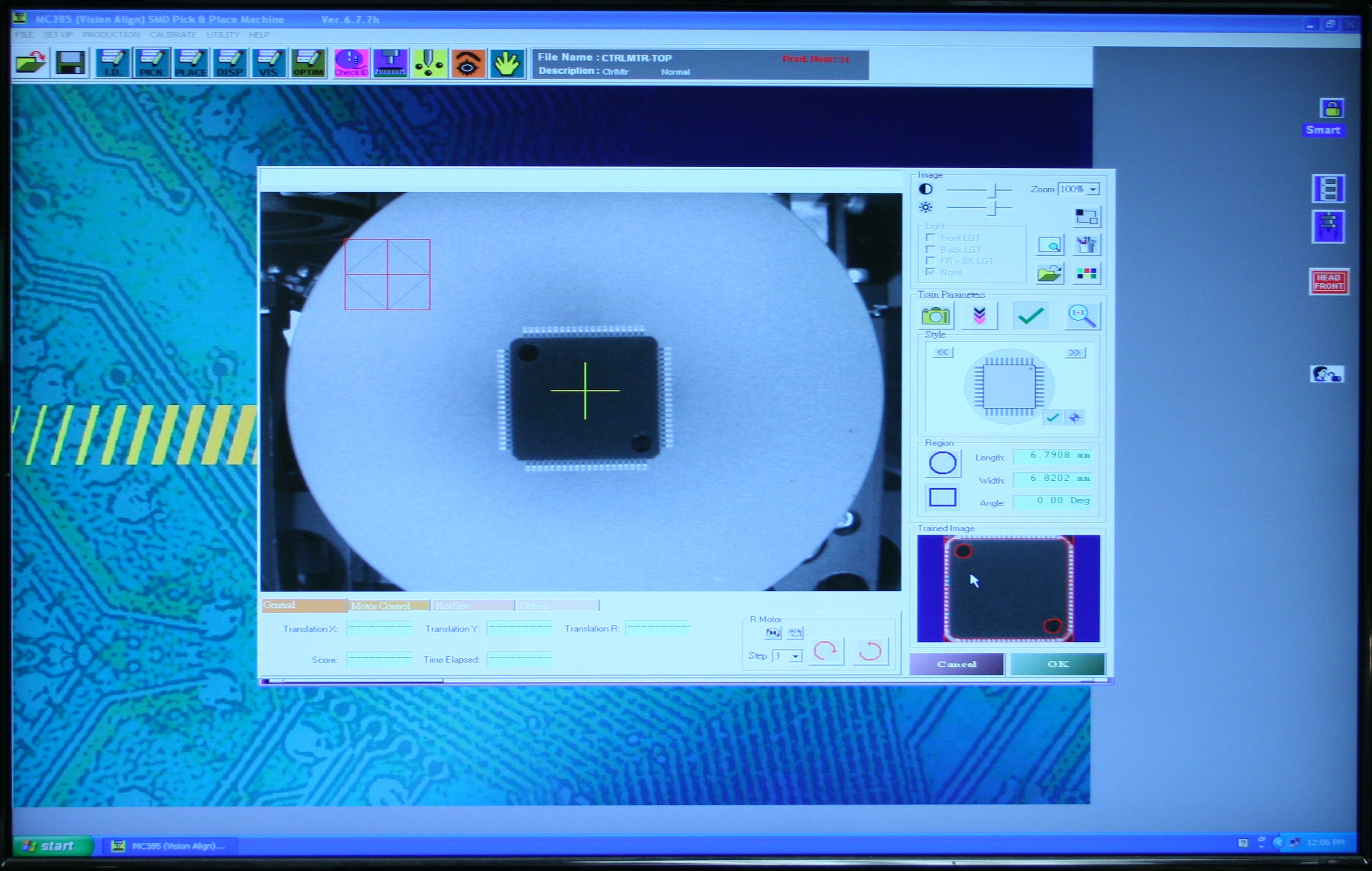
This exposes a problem: the part is no longer within the field of vision for camera A and the machine can't recognize it. I create a new reference image using camera G, which has a larger field of view but slows down production as the head now has to detour to the fixed camera G location before placing the part. The larger view also exposes another problem; the part is larger than the nozzle and the head is visible in the image. This background clutter could be hidden by using the large white N6 nozzle. The machine is still able to recognize the part with the smaller nozzle and I will continue with it. The practice run produces the expected result, the part is offset on the board.
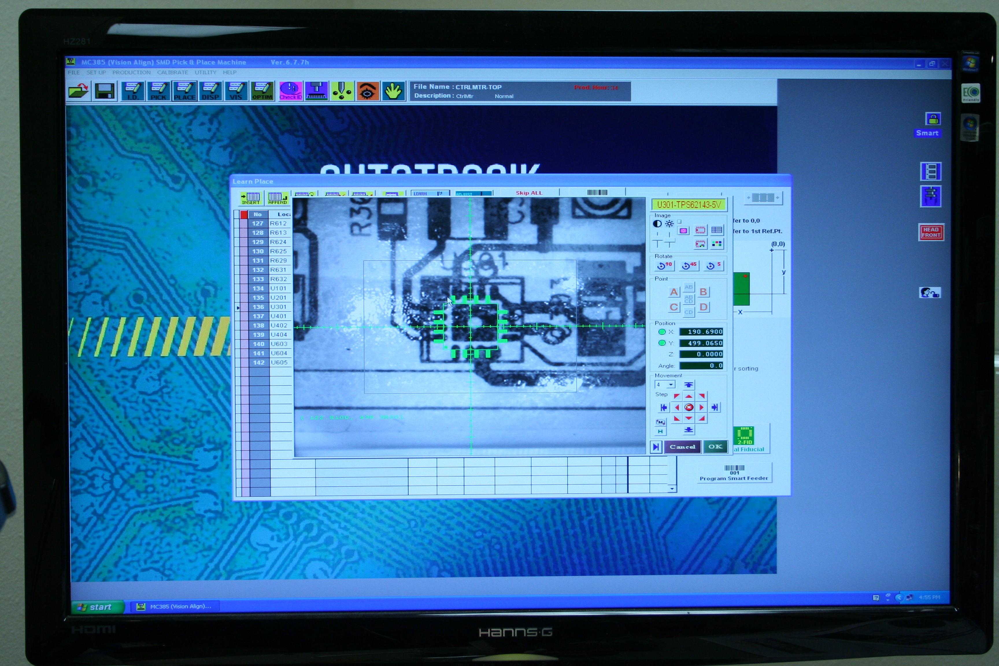
I create another reference image, this time using the cursor arrow keys and rotation buttons to carefully align the red crosshairs of the reference image between the 10th and 11th pins of all sides of the part. Using this reference image I am able to place the part perfectly even with the offset pick location. Note how far off the pick point (yellow cross) is from the reference center (red). The alignment is perfect even with the sloppy placement of the board in the work area.
I fill in the rest of the components by referencing the datasheets.
| English | Metric |
|---|---|
| 0402 | 1005 |
| 0603 | 1608 |
| 0804 | 2012 |
| 1206 | 3216 |
I finished the tray parts at 18:40. I spent a lot of time working out the pick angles and looking up exact dimensions from the datasheets. I am much more exact with the PnP component library this time.
I have every part loaded and defined but I have noticed some confusion in the nomenclature between the schematic, BOM, and PnP. Now is the time to fix it while it is fresh in my mind. Otherwise, I may repeat the same names in the next project. I will update the names in the schematic, renew the layout, export the PnP as a new project, import it into Autotronik, and rebuild the pick and place tables. Hopefully this won't take very long as I won't need to actually load any feeders, just fix the names.
I have the pick locations and reference images, now I need to review the place locations. I first review the place list to make sure the component and LIB names match. Then I run an auto-build and carefully examine all the placed parts for orientation and fit.
20:15> I am working my way through the auto-build, but am stuck on Q18. It simply refuses to recognize the part. I am taking a break for dinner.
23:00> I struggled with Q18 for over an hour. The problem seems to be that the part has rounded and shiny features that don't reduce down to consistent edges. Poking around in the advanced settings I finally found the solution, bumping the search timeout from 500ms to 1000ms.
23:20> Success! The auto-build finally completed successfully. Examining the finished board I see some problems.
Q1 Q2 Q3 Q4
All the other parts looked good.
0402 parts are too small, especially when placed on the tray. The biggest problems are that they pop out of their tape pockets, although the 1206 ceramic caps seem to act like Mexican jumping beans on the tray. I am worried that it is too easy to miss applying solder through the tiny stencil apertures. On the other hand, the machine seems to have no problem with 0402 once the pick height is set correctly, and they do save a lot of space on the top layer of the board. I think I may have accidently ordered some metric 0402 parts because some of them seem smaller than others. 0402 is 1mm x 0.5mm. Future designs will start with 0603 and later be optimized to 0402 when the design is proven; I don't need to jump straight to 0402 on the first version.
[-O-] <=o=> [-O-]
May 8 2016
13:10> Day 4 of Loading the Feeders. Today's task is to figure out why there were problems with the first build and fix them.
Part #52, CAP-0805-1uF (C401,C404) Digikey 587-1284-1-ND is missing from the pick list. It is present in the BOM and the Digikey order. I found them in the project kit, I must have simply overlooked the bag. I am adding it to the tray as Q22/222, mounting 10 pieces.
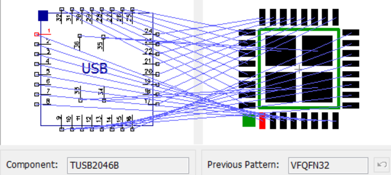
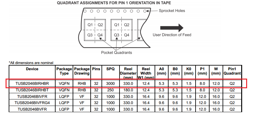
Part #7 was rotated CW90°. This the USB hub in FeederID 206. The tape orientation is Q2 and the pattern orientation is Q3, not the usual Q1. To rotate from pattern to pick counter-clockwise is 180°. The pick angle on Q06 was set to 270, which was wrong.
Part #9 was rotated CW90°. This is the MSP430F5528 VFQFN64 in Q21/221. The tape orientation is Q2 and the pattern orientation is also Q3, the same problem as #7. The pick angle should be 180 not 270.
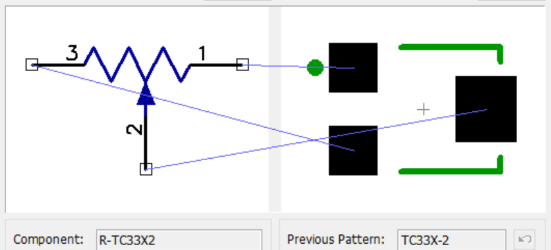
The TC33X parts were rotated 180°. The pattern has pin 1 in Q1, the tape has pin 1 in Q3. This is a 90° rotation, but the pick table has 270.
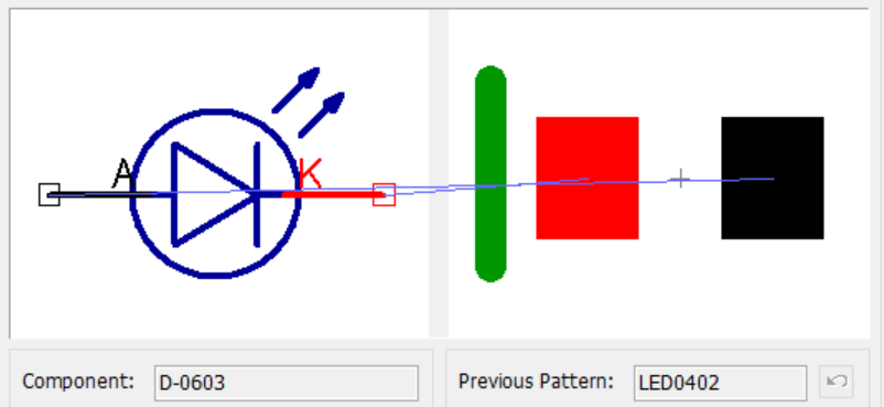
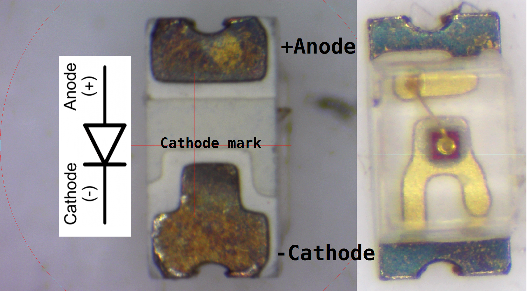
I want to make sure the tray leds are oriented properly. The pattern has the cathode to the left (Q1/Q3) and the tape has the cathode down (Q3/Q4) for a rotation of 90. The pick table was 270, which was wrong.
Part #12 TPS62143 (U301) in Q11/211 was slightly misplaced. This is most likely an offset in the PnP reference image.
I need to auto-build the problem parts to make sure they are fixed: C401,C404,U401,U101,U301,R512,R526,R540,D607. In Autotronik, I open the Learn Place window and click "Skip ALL". I click the "Location" header to sort by location and uncheck Skip for these components.
D607 had been set to RES-0402-150K, which was not right. I change it to FeederID 216.
This is a good time to review the entire place list for a sanity check: Are all the C components actually caps? Are all the R's actually resistors?
I place the reloaded tray and emptied board in the machine, reset all the tray QFN No cells to 1, set the pick locations for the new Q22 feeder, re-enable check fiducials (Setup > Learn PCB). Then I check the reference image for the USB hub in Q06.
I launch a new production run. The machine fails to recognize the TC33X and the reference image is rotated 180° from the current pick, making me think I may have loaded the parts into the tray the wrong way during the JumpMtr build. I created a new reference image and the build completes without any other problems.
Reviewing the board shows all the problems fixed. I verified that D607 is oriented correctly on the board. The only remaining problem is that it was U301 (TSP62143 in Q11) that was misplaced, not the USB hub.
I remove the components from the board and replace them in the tray, reset for another build. I just want to check U301, I click "Skip ALL" and uncheck only U301 for this build.
While resetting the tray QFN No using the "Learn by Camera" window, Autotronik presented a diagram for the polarized (tantalum) cap in Q16 (C104) with the + band up, opposite the part on the tray (band down). Clicking the "Rotate" button in the window spun the diagram to match the actual part and updated the pick angle from 90 to 270. The problem is that my pattern for the cap has the anode (+) pin to the left, so an actual pick with the anode down would be a pick angle of 90. I believe letting Autotronik "help" me by leaving the pick angle at 270 will result in misplacing the part by 180°. Let's find out....
The build is complete: U301 is still offset, there must be a problem in the place location. C104 is placed backwards, as expected. The lesson learned is that the pick angle is the rotation required to go from DipTrace pattern to actual PnP pick and I should ignore the helpful hints on the screen.
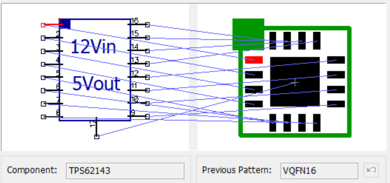
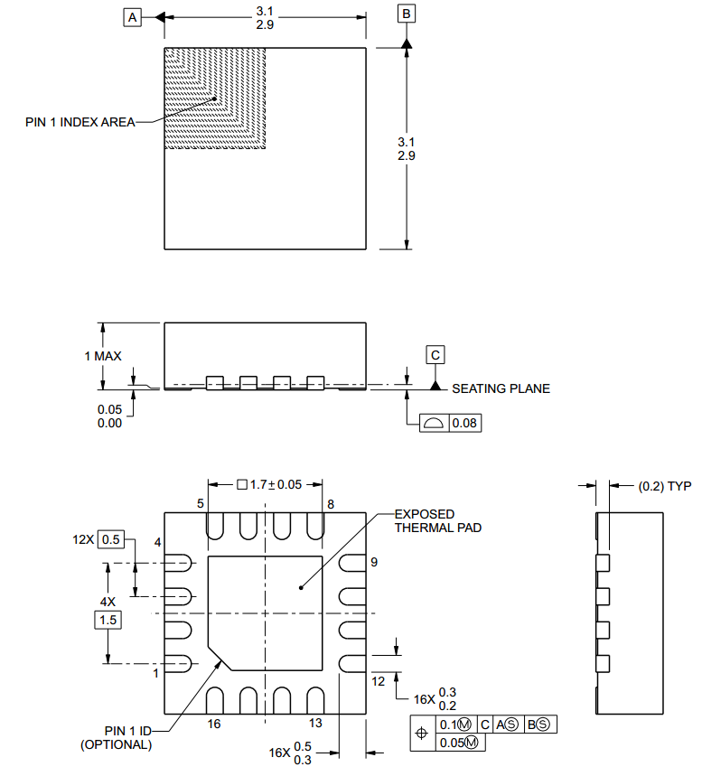
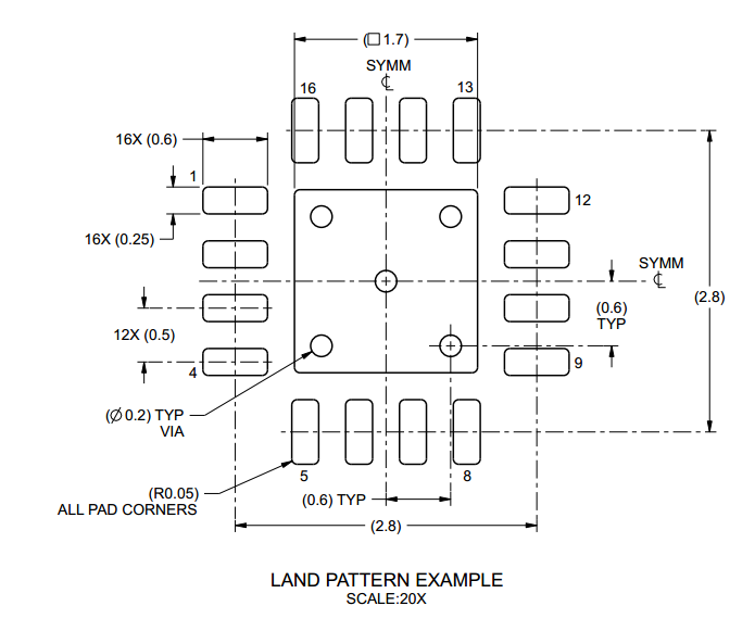
U301 is TPS62143, which uses the VQFN16 pattern. My pattern matches the land pattern at 2.8mm through the center of the pads, with the origin over the center of the part.
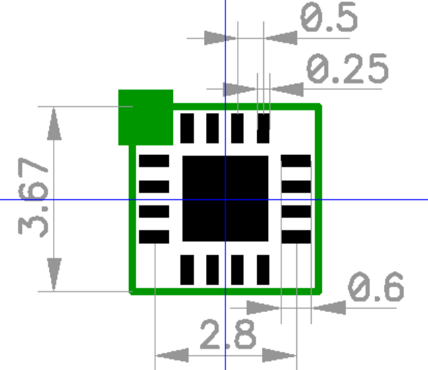
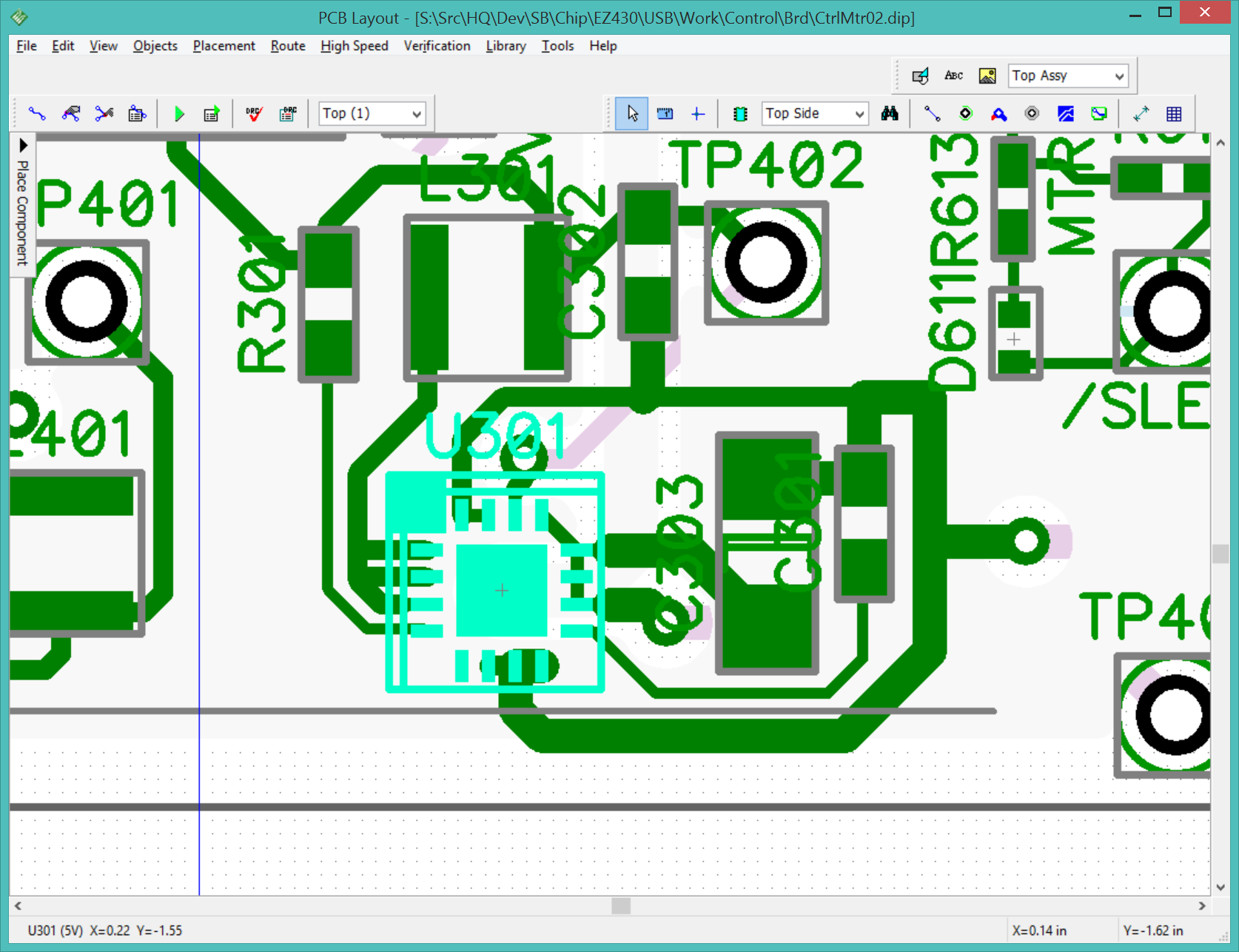
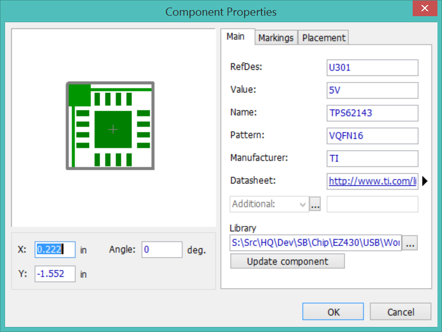
When I highlight the pattern in the layout, something funky is going on. It looks like there are two outlines of different sizes. I right-click the component in the layout and the component properties has an extra outline that isn't present in the component pattern, bumped out by the oversized pin1 marking. This might be the problem. I shave it down in the pattern, migrate the changes to the component, and update the layout.
I need to translate the location of U301 from DipTrace to PnP. They use different origins, so I will use a common point as the origin. The common point is DipTrace(F3) and PnP(Ref2). They also use different axes, DipTrace uses +X=right and +Y=up, while PnP uses +X=left and +Y=down. To translate from DipTrace to PnP: Subtract F3, flip both signs, then add Ref2.
DipTrace(U301)= (5.65,-39.42)
DipTrace(F3)= (-35.99,-11.68)
PnP(Ref2)= (231.87,470.78)
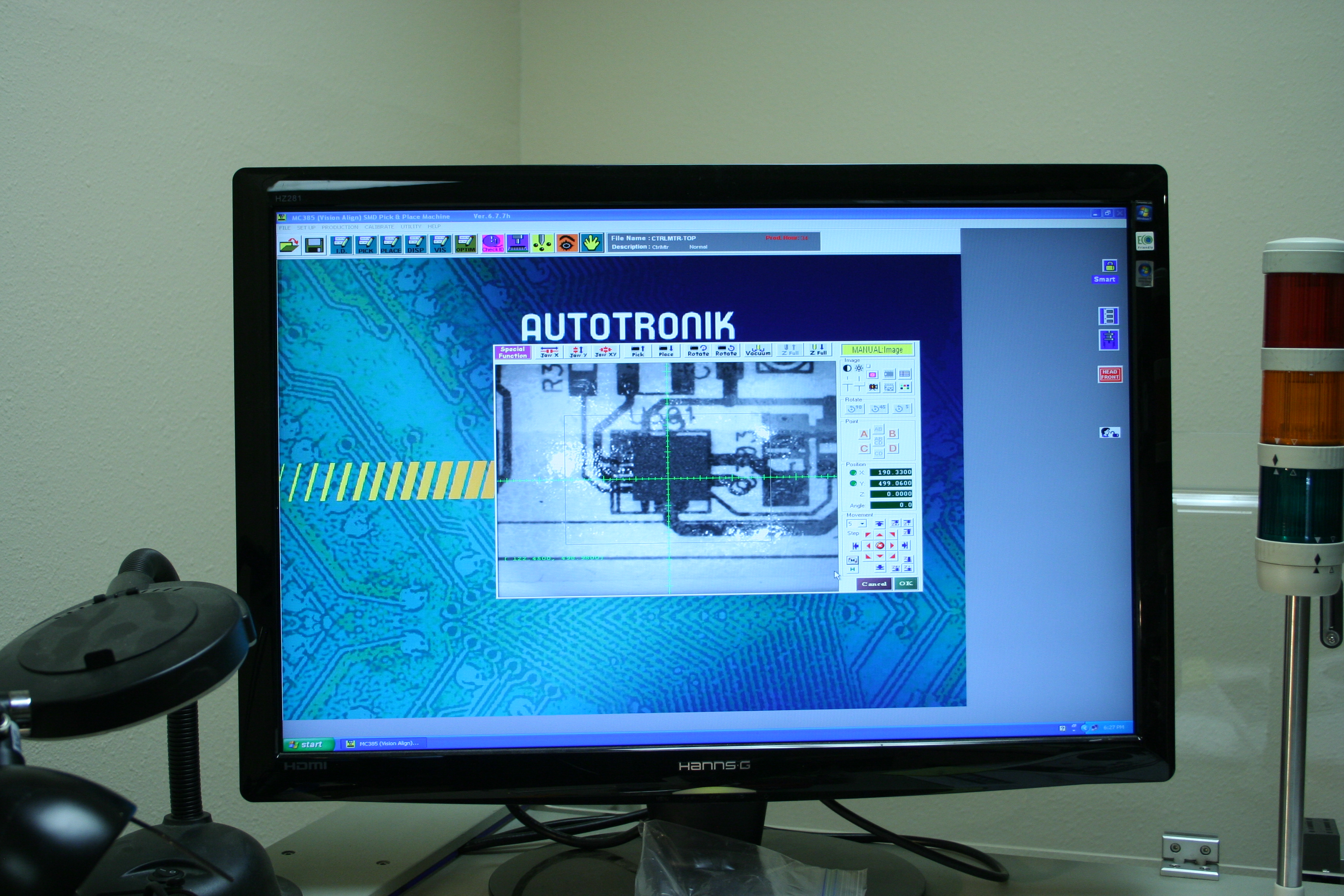
Calculated PnP(U301)= (190.23,498.52)
Current PnP(U301)= (190.69,499.07)
This would move U301 slightly right and up, which is correct. Rather than re-import the project (which is a significant task that will need to be done eventually) I will just hack the place location for U301 in the Learn Place window.
I run an auto-build for just U301 and the end result is a much better placement.
I am now confident the machine is good to go to crank out boards. The final test is a full production run with the expectation of a non-stop run to completion.
19:15> The full-speed production run completed with only one machine error and two operator errors. The machine failed to recognize U301 and I had to interrupt the build to create a new reference image. I forgot to update the pick locations for 2 tray components that I had moved, resulting in failed picks.
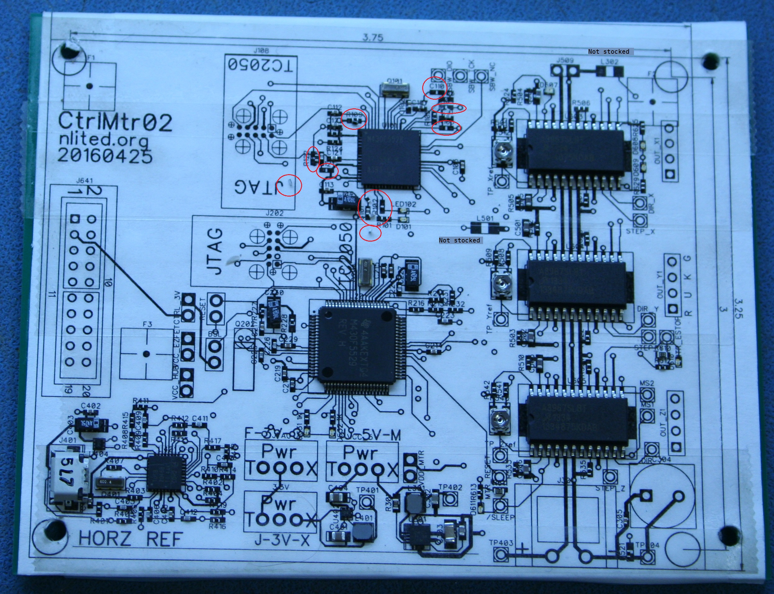
C110 is missing. R109 is double-stacked, probably a stray 0402 resistor from the previous build. R106 is missing. C111 bounced, this is located on a TDST seam that may have caused it. R104 is missing. R121 bounced. The problems are all in the same general area of the board, around the 5529. The missing pieces are in the place list, I am confident the machine placed them and willing to believe these may be due to using TDST as a proxy for solder paste; this was a board adhesion problem, not a PnP problem. While larger 0603 pieces might stick to the board better, this may be a problem that is specific to the paper board and would not occur in production.
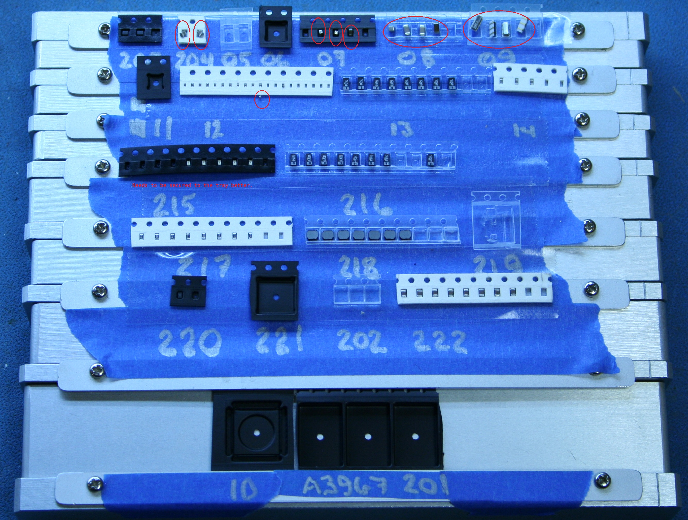
After the build, I found that several of the tray parts (mostly the 0603 and 0805 ceramic caps) had been bounced in their tape pockets. This would have resulted in failed picks on subsequent boards, which could only be remedied by halting the build, removing the tray and manually restoring the parts to their proper pick locations. This may have been caused by the head moving too fast over the tray and blowing the parts around; reducing the production speed may help. More likely, there is too much flex and recoil from the plastic tape, resulting in a springboard effect when the head picks a neighboring piece. This could be remedied by using TDST with stronger adhesive to secure the tape to the tray.
May 9 2016
I am going to try to fix the problems and reload for another production run. My fix for the bounced parts around the 5529 is to apply some fresh TDST in that area. The fix for the bounced tray pieces is to apply fresh TDST and a drop of Krazy Glue to bond the plastic component tape to the TDST and painter's tape under it.
10:10> I am clearing the pieces from the board and restocking the tray.
10:45> I finished clearing the board and restocking the tray. Restocking the 0603 leds is the worst, these should not be tray parts. To save time, since this is another non-functional paper board, I didn't worry about their orientation -- some may be backwards.
11:30> Resetting the tray pick.
11:47> Finished restting the tray. I checked every component.
11:50> Starting the production run.
12:05> Production finished. Failed pick on Q02 (TC33X), the second piece seems to be stuck in its pocket. Failed to recognize Q20 (TPS62143), this part seems to be a difficult image. Failed to recognize Q10 (MSP430F5529), this is a large part that requires camera G. The background clutter in the image seems to be the problem. I switched to using nozzle 7W with the large disk, which seemed to solve it.
12:15> I was able to place Q10. Q20 and Q02 still failing. Q02 (TC33X) was operator error, placed in the tray backwards.
12:30> Q20 finally worked when I switch to the smaller N1 and adjusted the brightness and contrast to a very dark image with low contrast, with only the pads visible. The original N2 nozzle was larger than the part and creating background clutter.
Final report: D608 bounced. There is physical interference between the micro-USB and C407, the layout needs to change. The TPS62143 (Q20) is a problematic image. Fresh tape seems to have reduced the bounced parts. The tray after the build looks better, although the 6MHz crystals still bounced around. I may want to think about switching to the through-hole version to avoid this problem, and the TH version is cheaper as well.
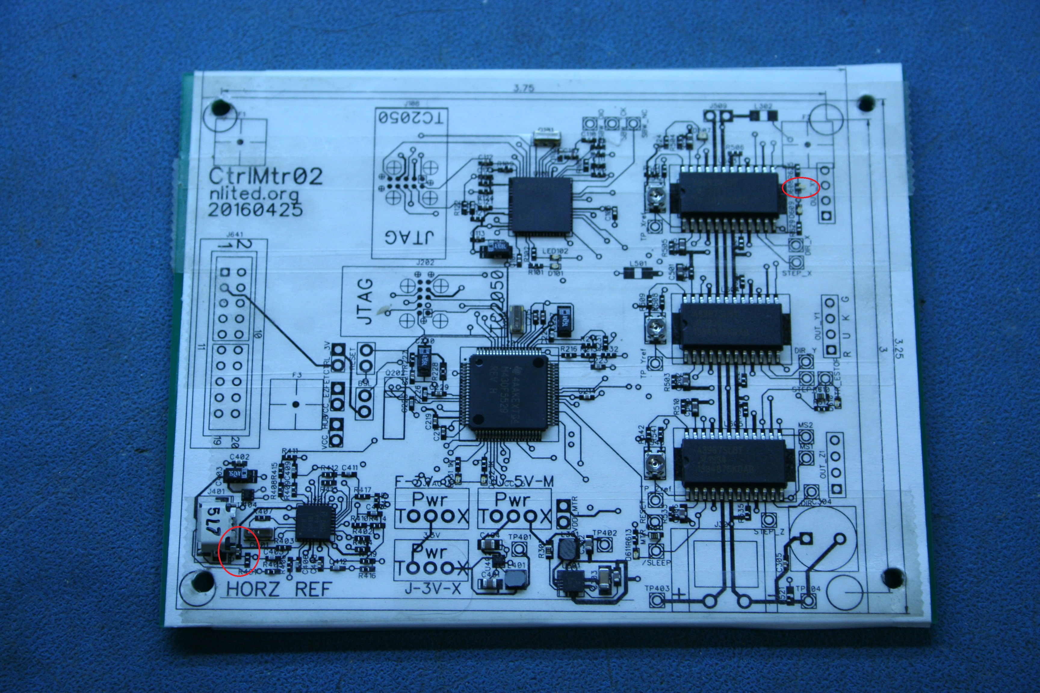 [Image 4255]
The big decision now is whether to plow ahead with the existing board using 0402 parts or take another week to replace the 0402 with 0603 equivalents, order the new parts, reload the feeders, etc. It comes down to the question: How confident am I that this unproven board will work if I build it with 0402 parts? Or conversely, how worried am I that 0402 parts will cause problems? I have built several working boards with 0402 parts, I know they work if I have everything set up correctly. The single biggest factor in the success or failure of 0402's is the proper application of the solder paste.
I am going to move forward with the current design, replacing the 0402 parts would be too expensive in time and money (and even more expensive if the board fails). However, for all future projects I will start with 0603 and optimize down to 0402 only when needed.
I need to tweak the layout just a tiny bit (move C407 away from the micro-USB). Then I can order the ferrite beads, boards, and stencil.
Some videos: