September 9 2014 - Chip
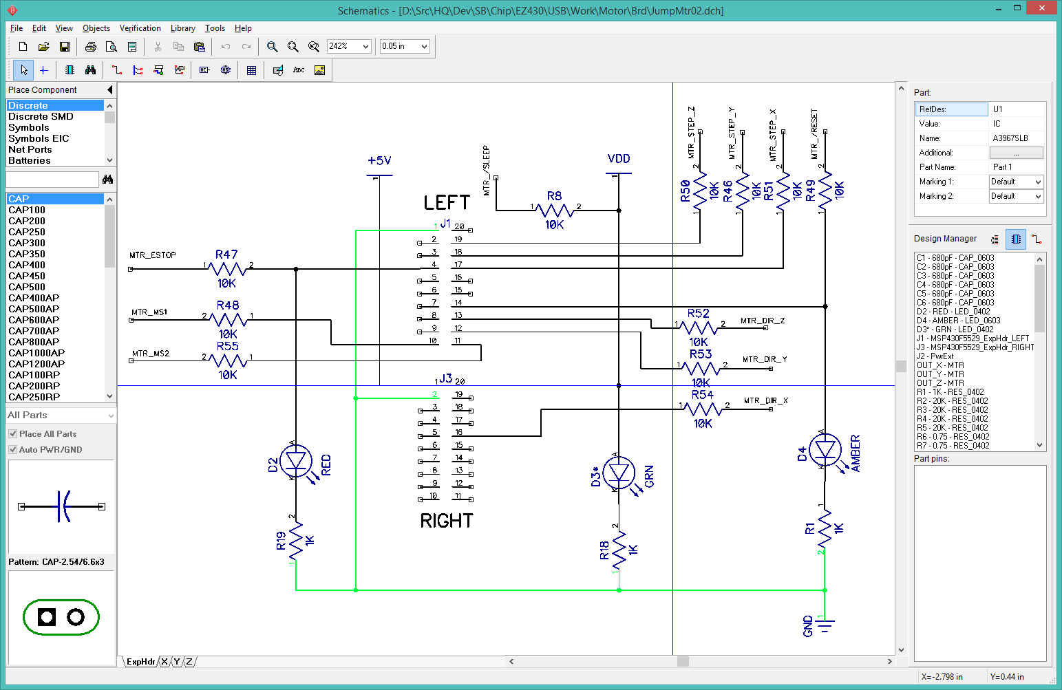
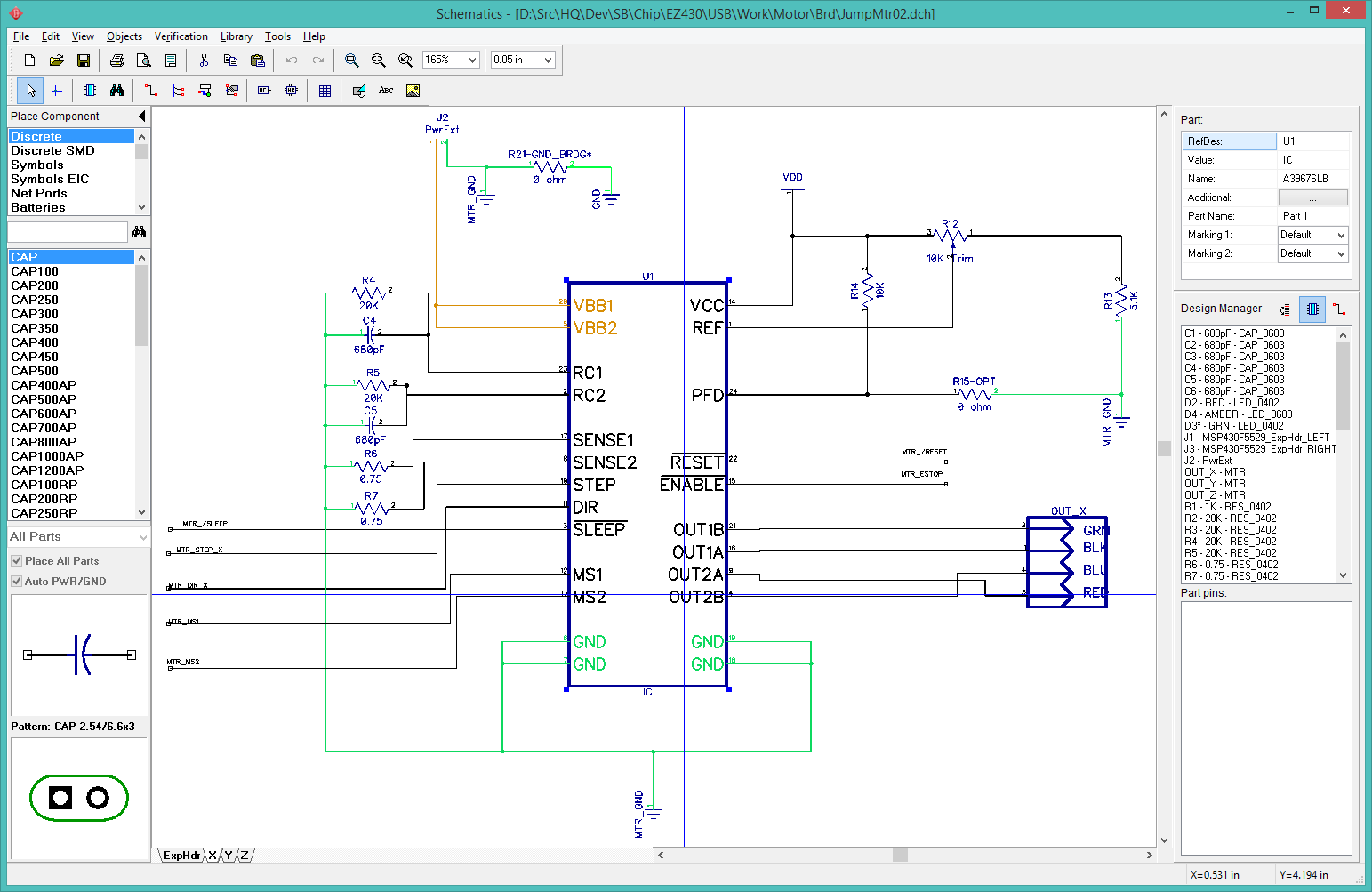
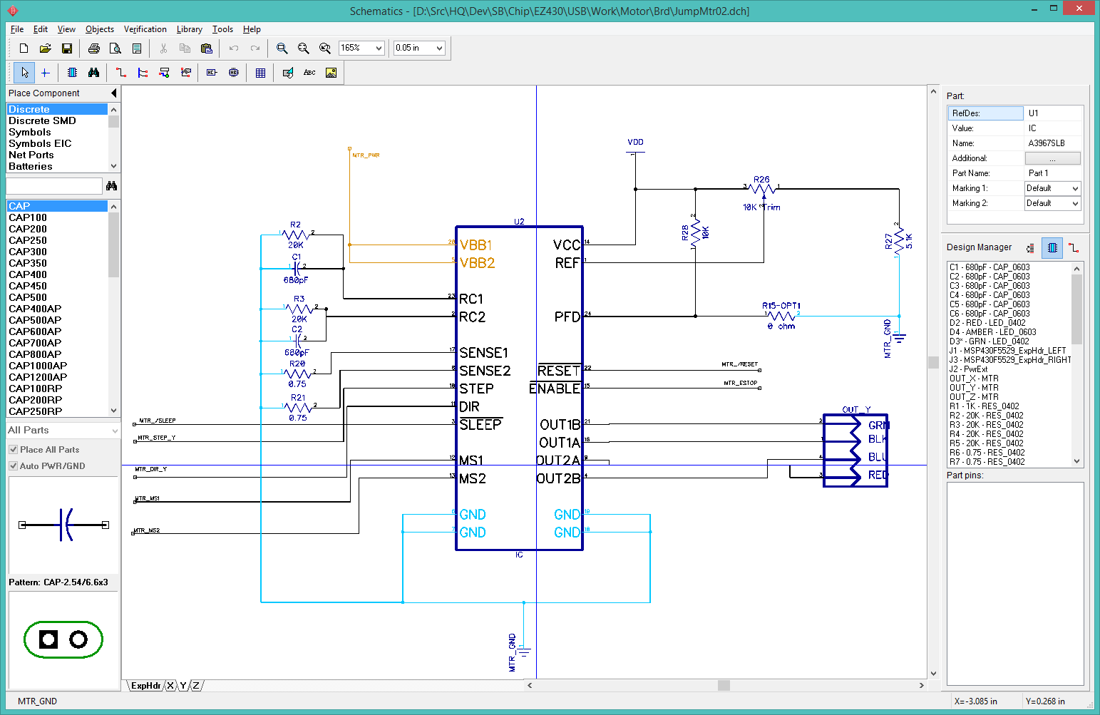
JumpMtr02 is my second draft of a "BoosterPack" board for the MSP430F5529 LaunchPad that provides a 3-axis stepper motor controller.
This is the schematic:
I converted the schematic to a PCB layout, copied in the board outline and heat sinks from JumpMtr01. DipTrace does not preserve the absolute coordinates when copying things, so I had to reconstruct most features by hand. This is not as bad as it seems, as the hard part was already done: determining the hard numbers.
I first dealt with all the physical constraints done, which included the board dimensions, location of the expansion headers, and locking the heat sinks to the motor controller IC's. I moved everything else outside the board outline to clear the workspace. I then saved this layout as JumpMtr02_Start.dip. This preserves this initial work in case I need to start the layout over again, which is fairly likely. Immediately after saving this file, I save it again as JumpMtr02.dip to make sure I would not overwrite the start file later.
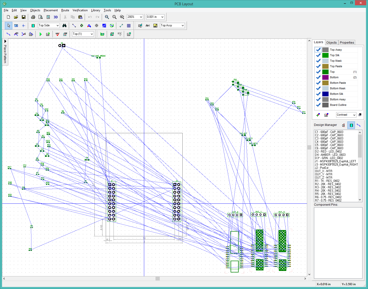
I first positioned the big pieces, the three A3967SLB motor controllers, the motor power input, and the motor power output jacks. The first traces are the big motor power lines.
I connected the common signal lines across the three controllers: MTR_MS1, MTR_MS2, MTR_ESTOP, and MTR_/RESET.
I placed the signal resistors near the corresponding header pins. I grouped the RC filter components around the trim pots and placed them next to each A3967SLB.
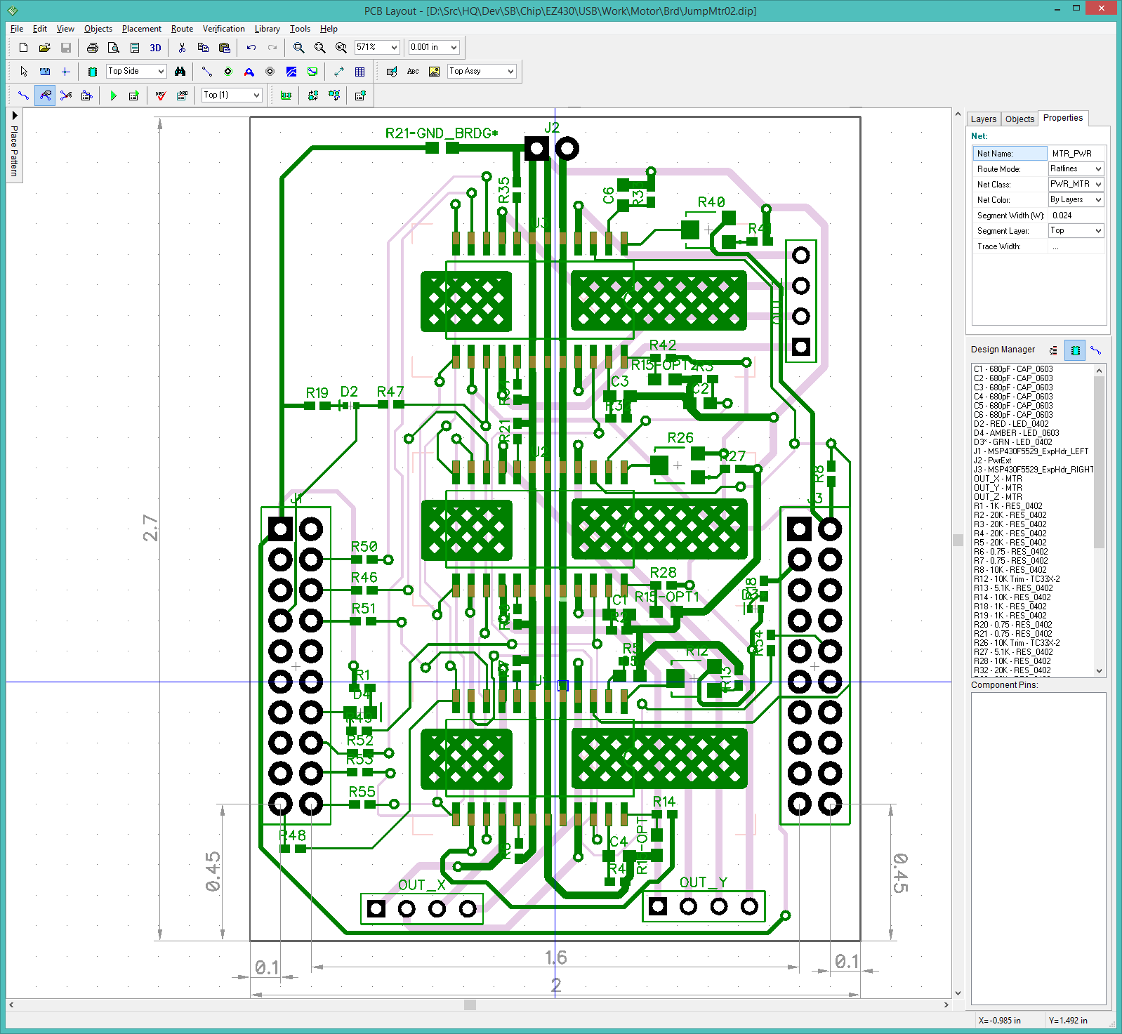
After about 3 hours of nudging traces around, I have the first version of the completed board:
A thought: Would a grid approach work? Try to keep top traces running north/south and bottom traces east/west. I think this would result in more vias as the signals wove in and out, but it might create a first complete routing faster.
The best approach seems to be placing the components in a rough grid alignment, then running the signal lines on the diagonals as much as possible. The worst case is to create an impassable wall of parallel signal lines on multiple layers.