April 9 2016
I spent the morning double-checking everything and doing the final assembly. The LaunchPad and JumpMtr boards snapped together with a perfect fit...
13:00> It is finally time to apply power to the finished board. The first test is to simply attach the USB cable and see if the 5529 still works with the JumpMtr board attached.
13:10> The 5529 is still alive. The simple switch/led program is still running. The green led D3 is lit, indicating 3.3V.
The next test is to see if I can turn on an led on the JumpMtr board. There is really only one option: D4 the amber led connected to MTR_/RESET:J1.14(Left):P4.3. I modified the JumpMtr program to write the switch state to both the LaunchPad led (P4.7) and the JumpMtr led (P4.3).
13:22> The amber led is blinking.
It is finally time to try to spin the motor. The motor is attached to the X controller. The following steps need to occur to spin the motor:
There is no point to doing anything else, so I connect the lab power supply and set it to 6V @ 200mA. This should be barely enough to turn the motor without a load, but not enough to cause the board to erupt into flames.
13:53> No joy. I cranked it up to 8V @ 500mA with no action. The supply shows 0A when I press the button. Hmmm.... time to hook up the scope.
15:30> I think the problem is the /SLEEP pin on U1 (X). It is always LOW (SLEEP enabled) even though R8 is at 3.3V on both sides. This makes me think that either the trace is broken between R8 and U1.3 or the A3967 is bad. The /SLEEP pin on U2.3 (Y) is HIGH, even though it is supposedly a direct connection to U1.3. This points toward a broken IC on U1. I need to toggle U2 to see if that IC is working.
15:45> U2 is cycling. I need to move the motor over to the Y connector.
I changed to code to toggle U2 step.
16:00> Success! The motor is turning when connected to U2. The motor needs 216mA at 6VDC to turn. 200mA is not enough.
I need to check continuity between the pad for U1.3 and R8 on a blank. The blank buzzes out OK. I buzzed U1 again and I was able to get a tone from the pad but not on the pin. This probably means a bad connection between the pin and pad. I am attempting to reflow the solder on that pin using a soldering iron.
16:30> I was able to connect pin 3, but the IC is still behaving very strangely. I suspect it is bad.
The motor is definitely geared for accuracy over speed. Top speed is about 4 or 5 RPM. Best efficiency with 3V @ 164mA. Worst is 4V @ 280mA. I left the motor running at full speed, 3V/164mA (0.5W), and the A3967 remained only slightly above room temperature.
I tried running the motor with 12V and it ran fine at 107mA (1.2W).
I have no idea where the other stepper motors are, so I am unable to create a full 3-motor demo. I disconnected the motor from U2 and connected it to U3. This also worked. I reconnected U1 with the same result -- no action. I believe the IC is broken.
=====
18:30> I am starting the build for board #2. I am confident the problem is a bad part and not the design. I had put the solder paste in the fridge and it will be at least half an hour before it has warmed up again, meaning it is time for dinner.
21:00> Starting the build on board #2. Loading the three TC33X parts took almost half an hour.
21:30> Applying paste. This takes only a minute or so to align the stencil, 30 seconds to scrape the paste, another minute to clean up.
21:35> Placing the parts. This takes about 2 minutes once everything is set up, another minute to inspect.
21:40> Baking the board. I cut and stripped the wire leads while the board was baking.
21:55> Final assembly: Mounting the wire leads.
22:08> Testing.
22:15> SUCCESS! All three controllers are working. I declare the JumpMtr design complete.
April 28 2016
I wasn't at all worried about being precise, I just wanted to see the motor turn. I needed to pay more attention to the details while trying to figure out why the microstepping modes were not working. This is my Delay() function:
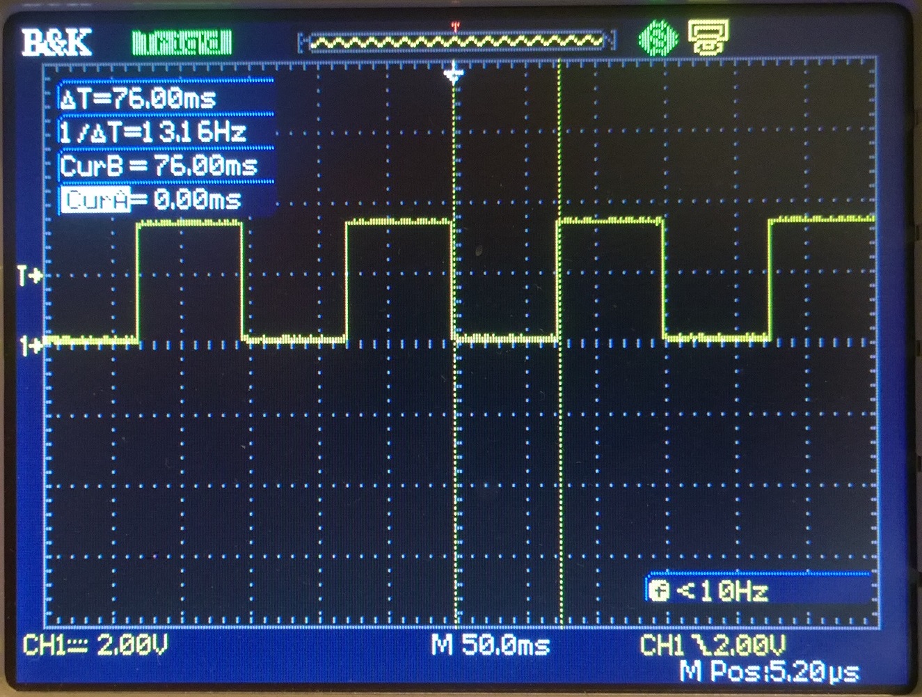
True to its micrcontroller nature, the period is absolutely rock-steady at 76ms per phase. 2000 cycles/76ms is 26316 cycles per second. Add some cycles for the overhead of the code loop and function call and this puts it in the ballpark of a sloppy 32KHz crystal. I can use 30us per cycle as a rough approximation. The actual number is roughly 25.2us per cycle.
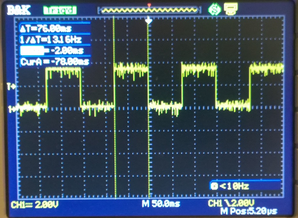
These clearly show the noise leaking into the MTR_STEP_X control signal. The first is with no motor power, the second is with power.