The schematic was easier than expected, I was able to finish the first draft of the entire board in just another 30 minutes. The schematic is quite simple, just the expansion headers, three indicator leds, and three instances of the A3967SLB circuit.
I opened the BlinkMtr02 project in one window and the JumpMtr project in another, then copy/pasted the led components into the ExpHdr page. The X page was even easier, just copy/paste the entire Driver page and then edit the MTR_STEP and MTR_DIR nets to add the "_X" suffix. I also needed to rename Vcc to VDD.
For the Y page I copied the X page, renamed MTR_STEP and MTR_DIR, then deleted the PwrExt jack. The Z page was a straight copy of Y.
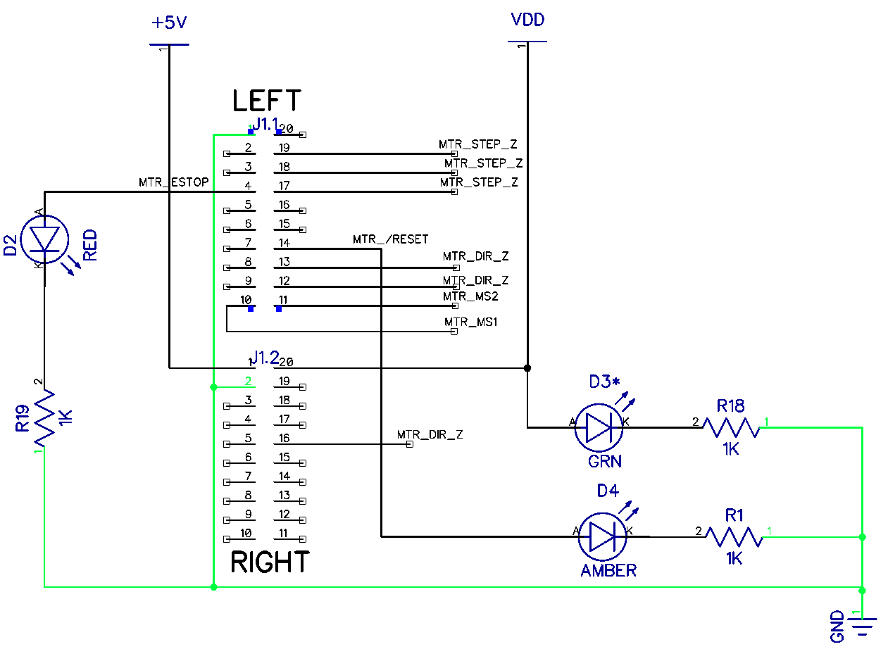
This is the expansion header page:
The first draft.
NOTE: The control pins are WRONG! This frequently happens when I re-insert a component; either I forget to rename the new nets or I do rename the nets and inadvertently rename nets across many pages. In this case, when I added the new ExpHdr component I renamed all the control nets to _Z. This happens when I forget to check the box that "rename this wire only."
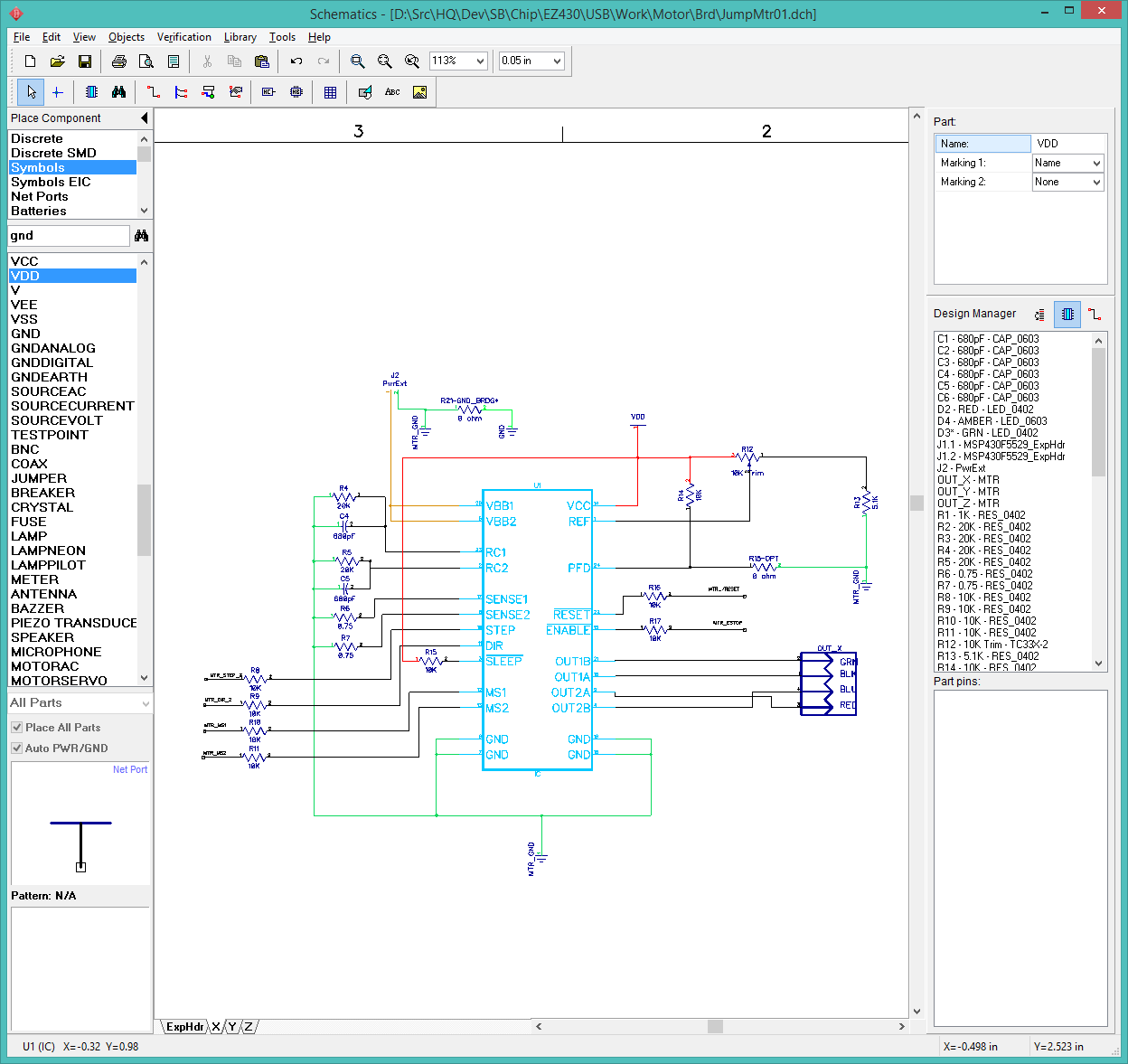
This is the X-axis page, which includes the motor power connector:
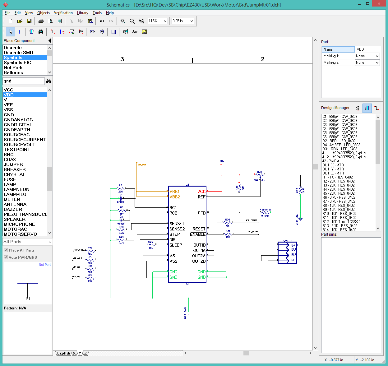
The Y and Z axis pages are identical except the MTR_STEP_ and MTR_DIR_ connections:
I am setting the project aside now, as it is 11:12pm and I have a full day ahead of me tomorrow. I started the JumpMtr project around 3pm this afternoon, so I have put a full day into it. This is much slower than normal as I am trying to fully document the entire process as I go along, rather than just the finished product after it is finished.
Next step, the layout.
{THREAD_LINK:1450}: Investigation into noise on the MTR_STEP_X signal.