April 9 2016
I need to double-check how the JumpMtr board is intended to mount onto the LaunchPad before assembling the headers. For example, LaunchPad P8.1 goes to header pin L19 that should mate to JumpMtr MTR_STEP_Z. Looking down at the LaunchPad (See {THREAD_LINK:1238}) P8.1 is the bottom-right pin on right header.
I designed JumpMtr to be mounted onto the LaunchPad back-to-back so that the top layer of each board would be exposed and easily accessible. The headers on the JumpMtr would be male pins extending from the bottom of the board and inserted into the female headers on the bottom of the LaunchPad. I can verify the design by simulating a view from the bottom of the JumpMtr board in DipTrace (View > Mirror). Looking down at the top of the actual LaunchPad board, all the header pins should match the mirrored view of the JumpMtr board. To my immense relief, this is true and I am "good to go" to mount the 2 2x10 0.10" male headers to the underside of the JumpMtr board.
[Photo of LaunchPad and JumpMtr back-to-back]
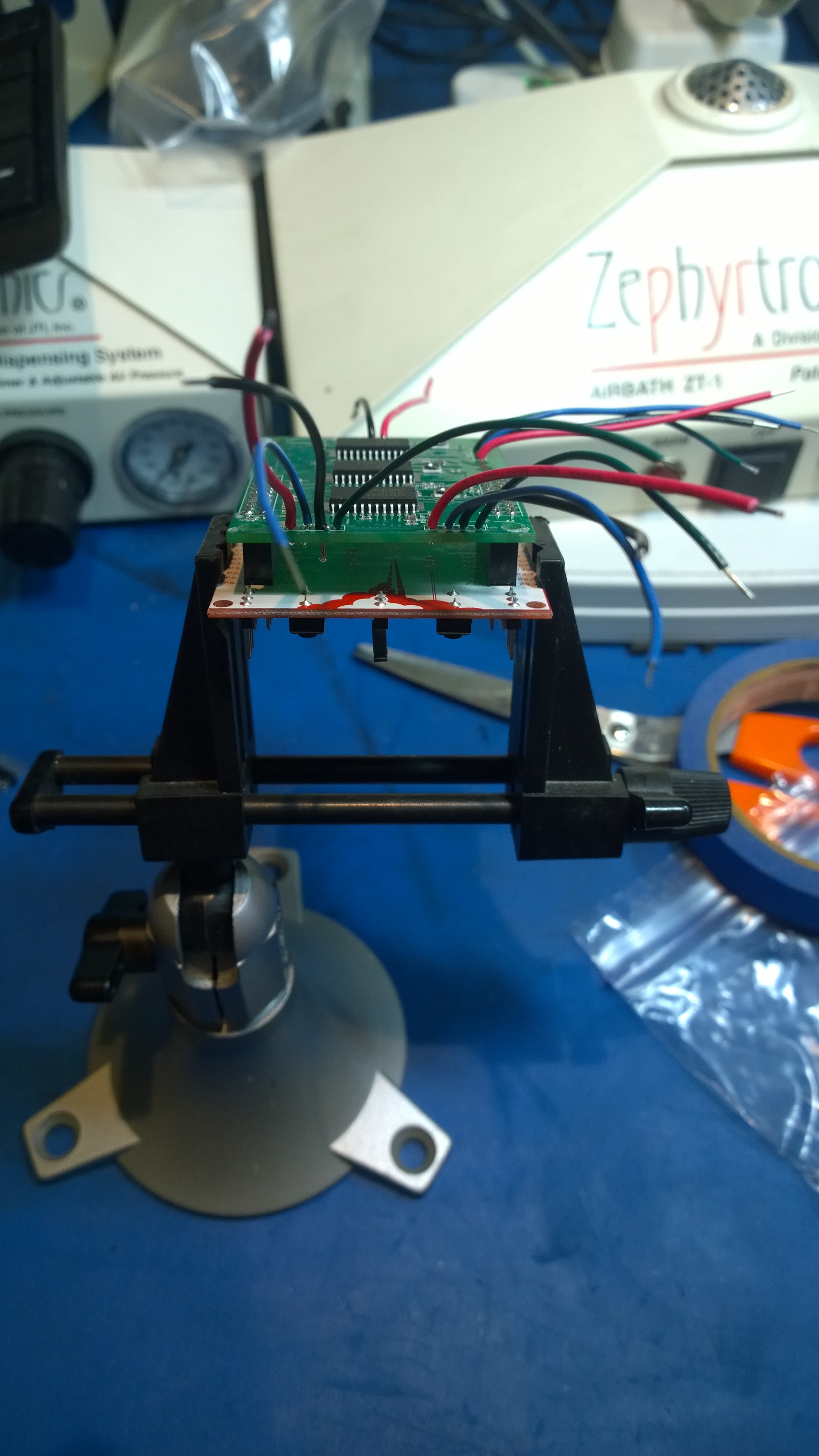
To verify the motor output connections I need to find my test motor and look at how the wires are terminated. The motor has long leads that end in bare wires, RED, BLACK, GREEN, BLUE. Since I am not 100% confident in my translation between all the different motor nomenclatures (there are at least three: {THREAD_LINK:1171}) I will attach bare wire leads to the JumpMtr and use a temporary wire splice to connect the leads.
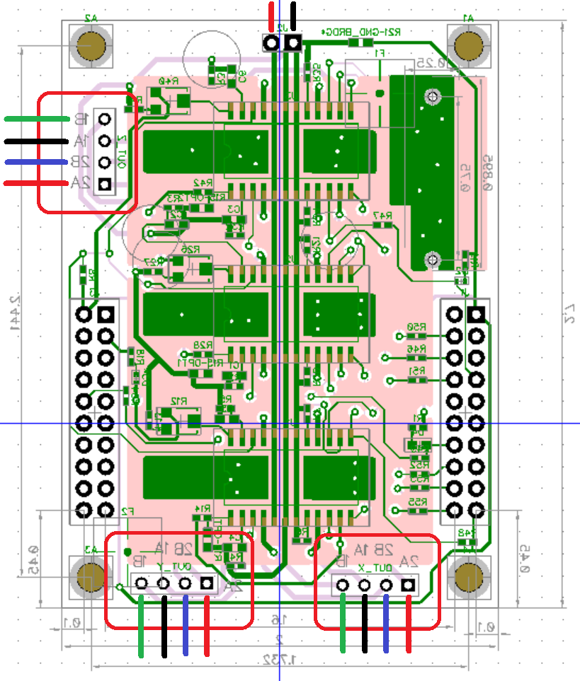
| Wire | MotorOut | A3967 |
|---|---|---|
| GRN | -A | OUT1B |
| BLK | -B | OUT1A |
| RED | +B | OUT2A |
| BLU | +A | OUT2B |
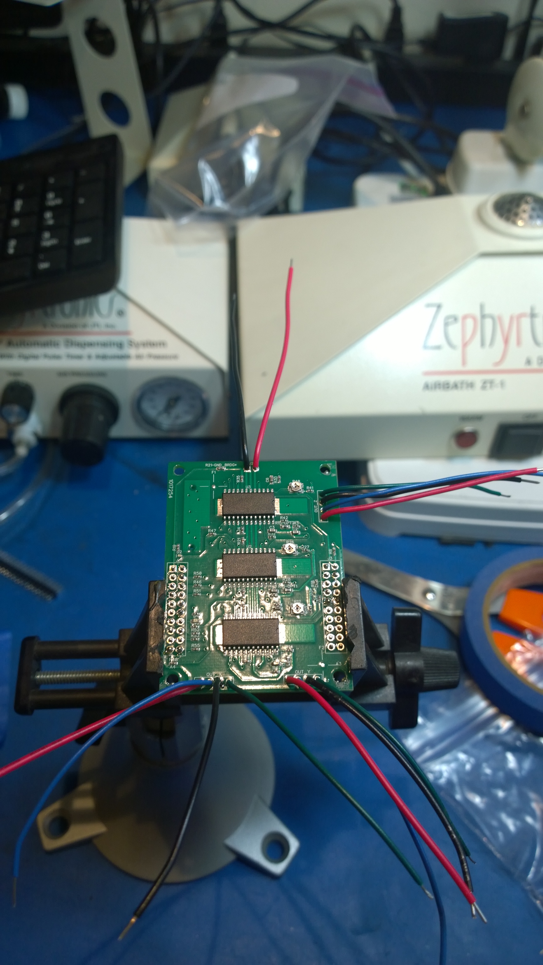
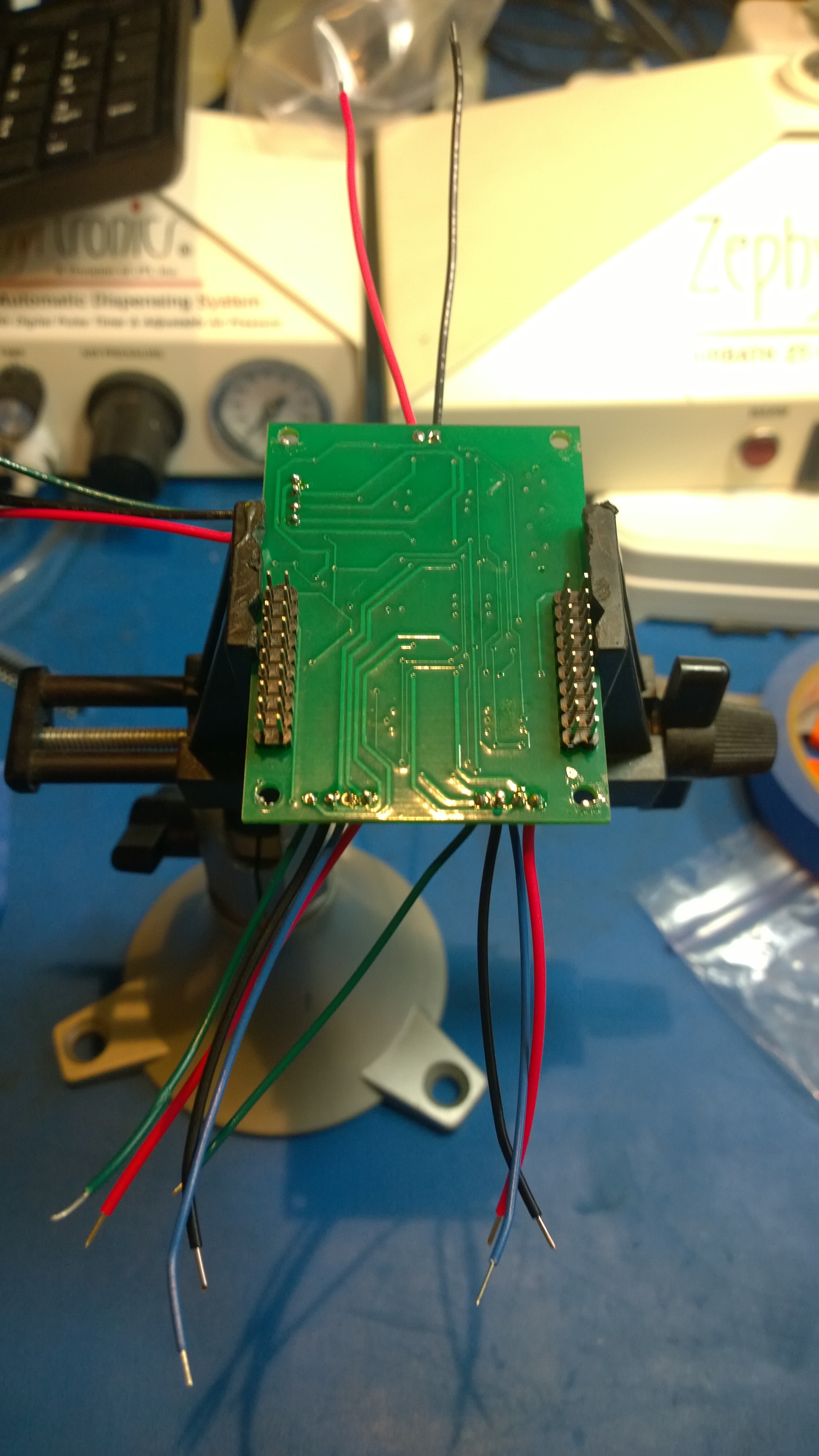
This is the how to mount the motor leads, looking up from the bottom of the JumpMtr board. The wire should be 20 gauge solid-core.
These will be 2" wires soldered in place with the tips stripped to reveal 1/4" of bare wire. I will then use alligator clips to connect the wires to the power supply.
BLACK wire to the square hole in J2 (MTR_GND)
RED wire to the round hole in J2 (MTR_PWR)
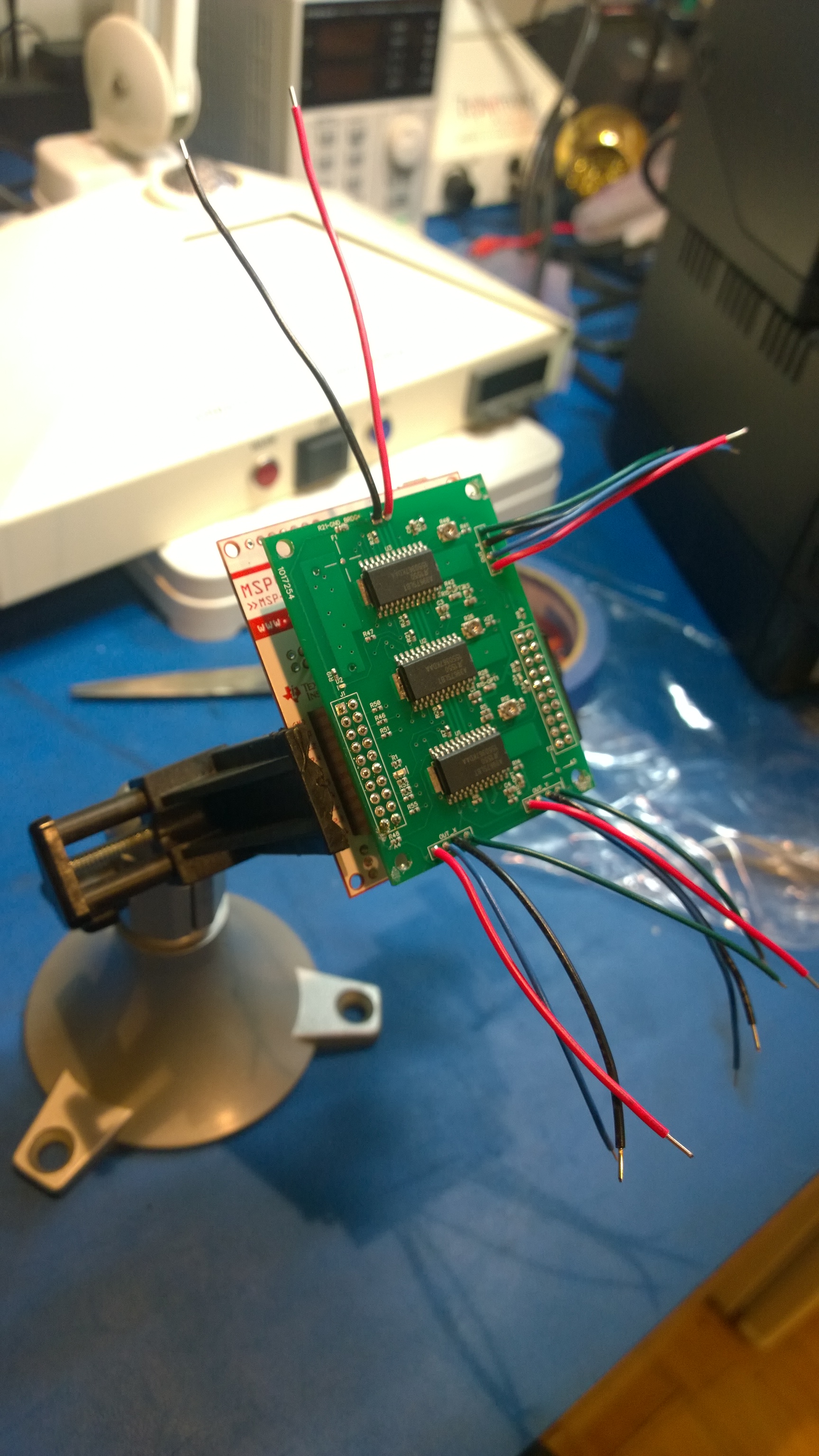
After mounting the motor wiring.
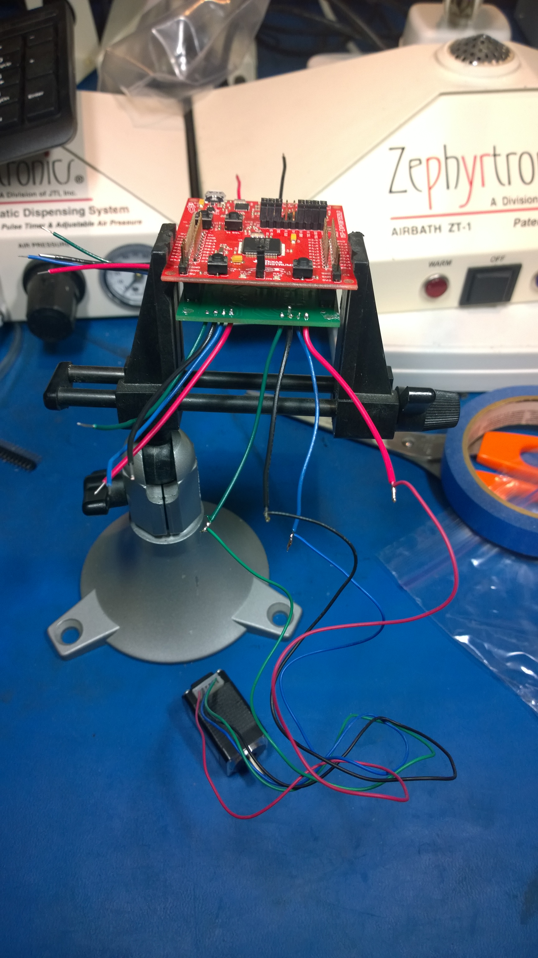
Here is the final product, with the LaunchPad and JumpMtr boards mated together.