2014-09-02 04:08:17 chip
Page 1111
📢 PUBLIC
The only real physical constraint for the JumpMotor is that it
needs to plug into the expansion headers on the LaunchPad board, so
that is where I will start with the schematic and eventually the
layout as well.
LaunchPad Expansion Headers
These are the usual 0.10" headers, 2x10 x2. This is a simple
component to create from scratch:
- Component > Add New to Library
- Set the component properties:
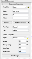
- Assign the pins:
Now I need to make my first big design decision! Do I want the
JumpMotor board to have its components "face out" or "face in",
and do I want the JumpMotor to be on the top or bottom?
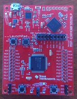
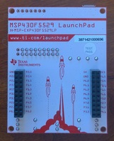
- "Face out" and bottom: the components will be easier to test but
board might be awkward to use.
- "Face out" and top: Components will be easy to test, the motor
connector will be easy to use, but the JumpBoard buttons will be
inaccessible.
- "Face in" and top: No advantage to this!
- "Face in" and bottom: Normal orientation, but the components will
be inaccessible and the motor connector will need to be either out the
bottom or right-angle out the side.
Since this is an experimental board, ease of access wins. The
JumpMotor board will be face out on the bottom. This means the header
pins on JumpMotor board will be male with the long ends protruding
from the bottom of the board, plugging into the female headers on the
bottom of the LaunchPad board. The pins need to be oriented with the
bottom of the LaunchPad. Looking down on the top layer of the
JumpMotor, the upper left pin will be GND and the lower right pin will
be P4.1.
So I assign the pins, working counter-clockwise from the upper left
corner; starting with GND and ending with P2.5. Note that I changed the
"Part" name to "LEFT".
UPDATE: I should have created left and right parts by clicking
"Component > Add New Part" before assigning the pins. There is
no way to copy a component into a part, so I had to delete the components
and start over.
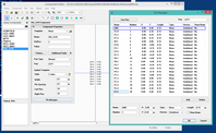
I create the right-hand header:
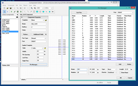
Save the updated component library
Finally, I place the LEFT and RIGHT headers in the schematic.
First, add the JumpMtr library: Library > Library Setup...
Then place the components, making sure "Place all parts" is checked.
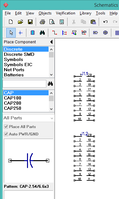
WebV7 (C)2018 nlited | Rendered by tikope in 98.788ms | 216.73.216.181


