Schematic PDF [FILE 7016]
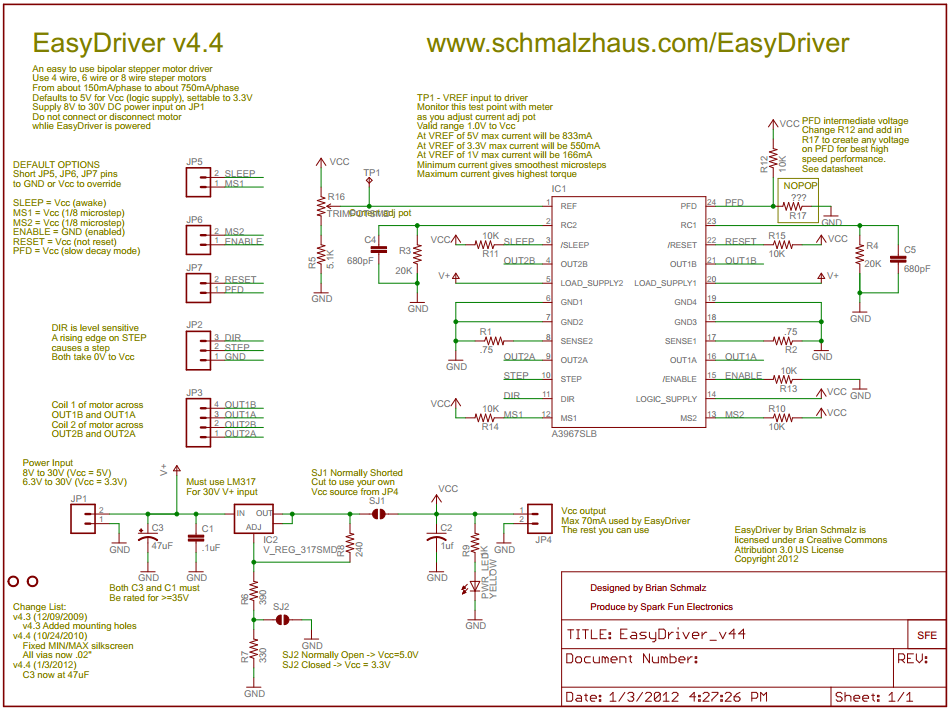
Now I have a proven, known good, baseline MSP430 board design. The "World's Simplest" goal has been achieved. :) For my next trick, I want to turn a motor. The motor driver circuit is based on the "EasyDriver" project by Brian Schmalz.
Schematic PDF [FILE 7016]
BlinkyMtr 1.0 will have the following enhancements:
Remove the external power selection header. This proved to be an unnecessary production step.
Add (leaving the existing 14pin header in place) a Tag-Connect header. This will remove the assembly step of mounting the 14pin JTAG header. Once the Tag-Connect is proven, I can remove the 14pin header.
Add the Allegro A3967 (A3967SLBTR-T) driver to the board. (Digikey 620-1140-1-ND) For this version I will hardcode the MSP430 to drive it in a set direction; I am only interested in knowing that I can turn a motor at all. The next revision will add push buttons to interactively control the motor in real-time. The A3967 will require a separate 12VDC power input for the motor.
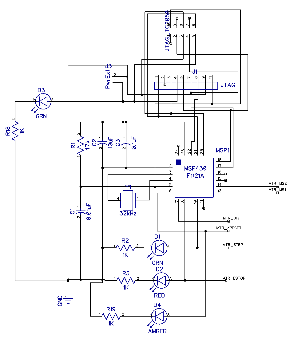
The basic MSP430 schematic changed a bit: I removed the TP9 header, removed the power selection header, added the Tag-Connect header, and added two more LEDs.
I added the Allegro motor driver as a separate schematic sheet. The trick was to name the nets consistently, which will tie them together in the layout phase. Of special note, I created a separate MTR_GND net tied into the MSP430 GND through a 0-ohm resistor. This allows me to not place the part if it causes a problem.
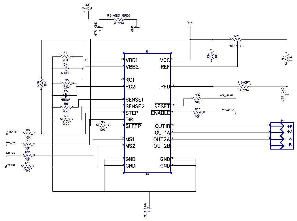
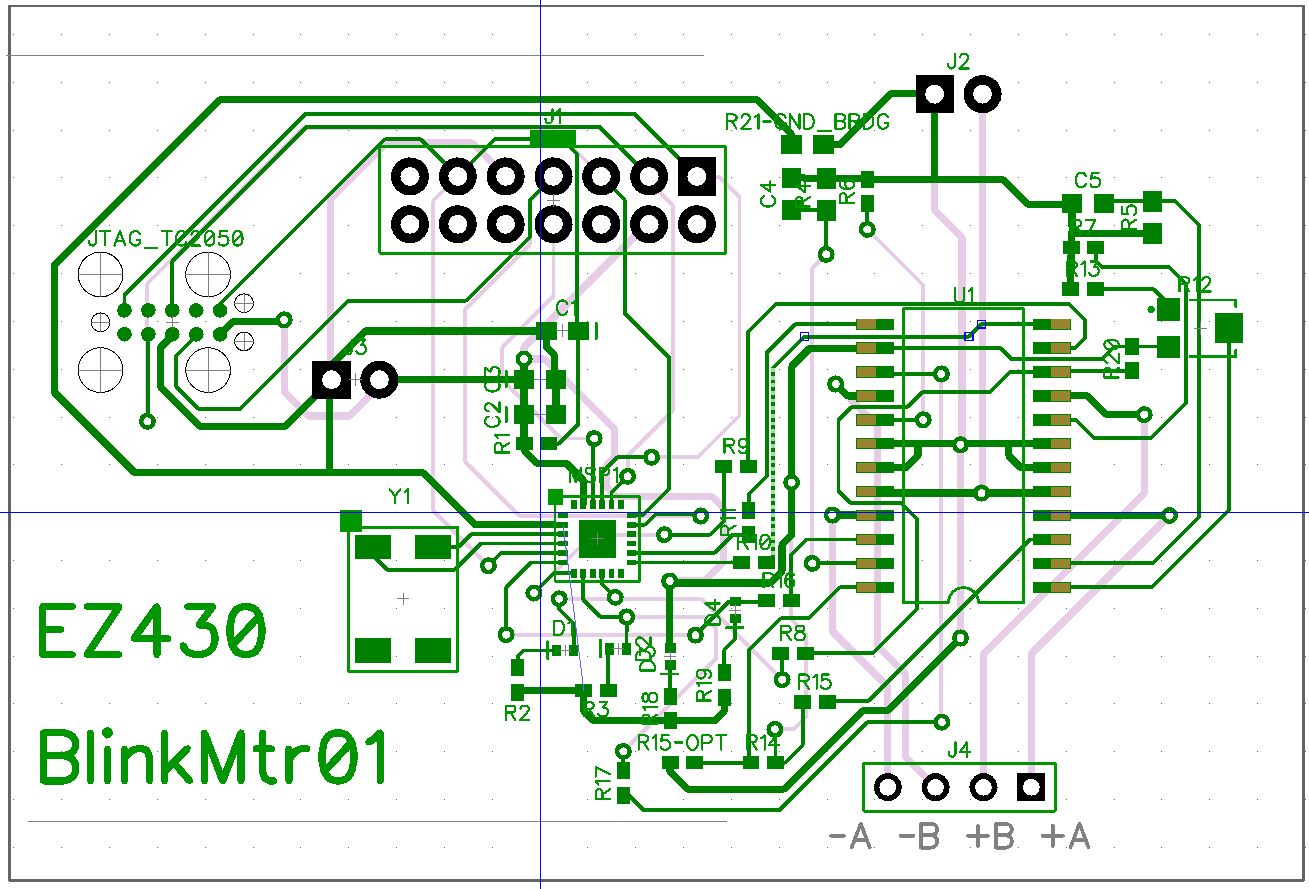
The layout took about four hours, including the creation of the Tag-Connect component and pattern and importing the A3967SLB component and pattern from Ron's library. I lifted the A3967 circuit directly from his schematic, I hope it works. Note that both the JTAG14 and Tag-Connect headers are included. Once the Tag-Connect header proves to work I will remove the JTAG14. I intend to build the first board without the A3967, just to prove that the Tag-Connect interface works. [Update: R20 is a mistake!]
I still need to confirm some of the parts and update my BOM spreadsheet to include the new parts. Then I will need to add the new parts to my PnP configuration.
I expect this board may get very hot, but the purpose is to prove the control circuit, the new JTAG connector, and increase the complexity of the PnP project a small step. I will be happy if the motor turns at all, which will be enough to write the MSP430 code to control the driver.
TODO:
I worked from home today. It was sunny and hit 80 until a high overcast moved in around 4:30.