2014-07-21 20:07:48 chip
Page 1080
📢 PUBLIC
Now that the controller is working it is time to connect to the
REAL WORLD and move something!
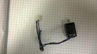
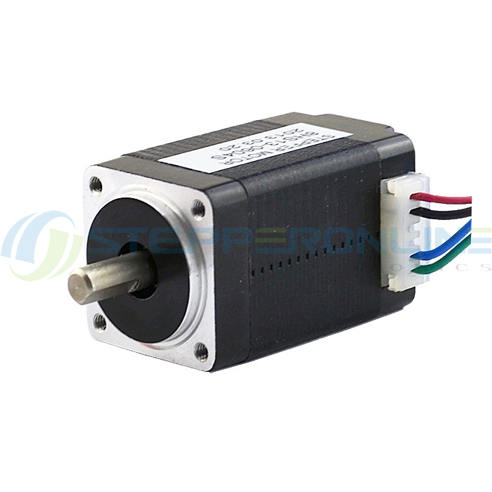
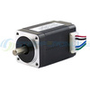 I am connecting to a Nema8 bipolar miniature stepper motor
(8HS13-0604S)
. This is a relatively small, strong, and heavy motor. It is not
suitable for any sort of flying aircraft and probably not good
for battery power. But it is common, cheap, and a good representative
of a lot of bipolar stepper motors.
I am connecting to a Nema8 bipolar miniature stepper motor
(8HS13-0604S)
. This is a relatively small, strong, and heavy motor. It is not
suitable for any sort of flying aircraft and probably not good
for battery power. But it is common, cheap, and a good representative
of a lot of bipolar stepper motors.
| Electrical Specification
|
|---|
| Part Number | 8HS13-0604S
|
| Motor Type | Bipolar stepper
|
| Step Angle | 1.8 degrees
|
| Holding Torque | 2Ncm (3oz.in)
|
| Rated current/phase | 600mA
|
| Phase resistance | 6.5 ohm
|
| Recommended voltage | 12-24V
|
| Inductance | 2.2mH +/- 20% (1KHz)
|
| Physical Specification
|
|---|
| Frame size | 20x20mm
|
| Body length | 33mm
|
| Shaft diameter | 4mm
|
| Shaft length | 10mm
|
| D-cut length | 7mm
|
| Number of leads | 4
|
| Lead length | 300mm
|
| Weight | 70g
|
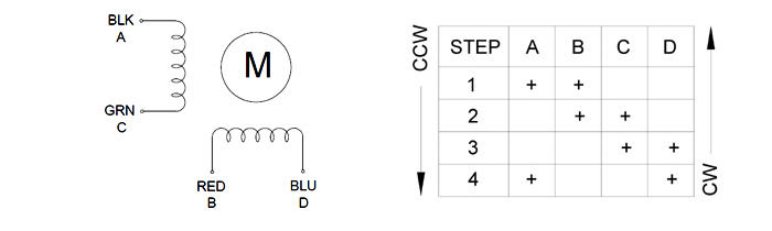
Connectors: A=BLK B=RED C=GRN D=BLU
This is the wiring diagram for the stepper motor:
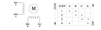
I believe this is the translation through all the different
names for the wires:
| ABCD | A+B+A-B- | Colors
|
|---|
| A | A+ | BLK
|
| B | B+ | RED
|
| C | A- | GRN
|
| D | B- | BLU
|
Which, of course, means my J4 output jack is incompatible
with the wiring harness on the motor. :(
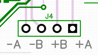
J4 should be RED/BLUE/BLK/GRN which is B+/B-/A+/A-.
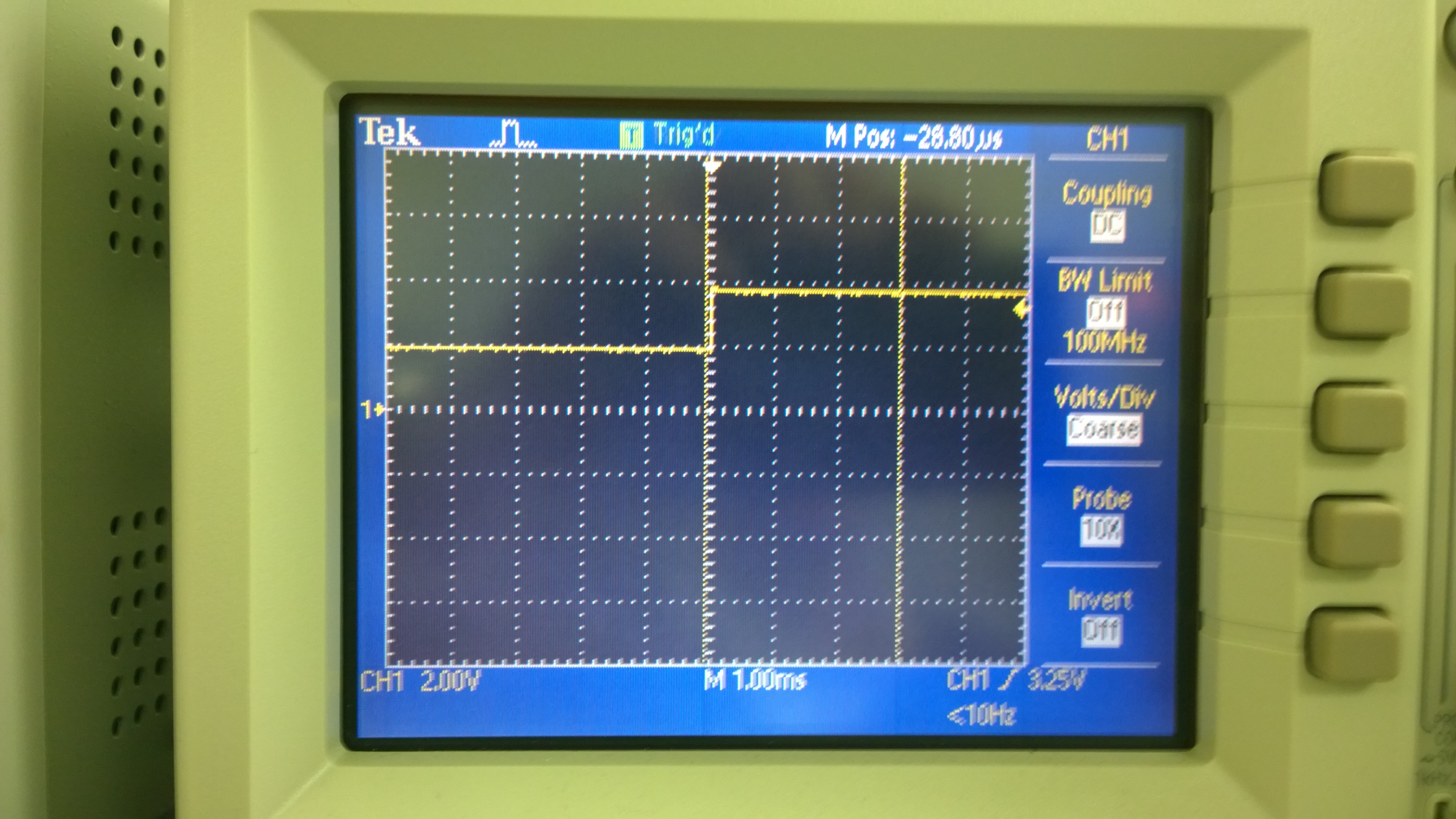
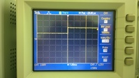
I cobbled together this test rig:
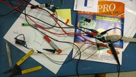
The motor does not turn. The driver did pull current (and get hot!)
sometimes. The scope on the motor output shows it is always
high. The scope on the driver STEP input shows it toggling between 2V
and 3.7V. I do not understand why the STEP signal does not go to 0V.
I think that is my problem.
Reviewing the schematic reveals that R20 was a mistake. I have no
idea why I thought STEP should be pulled high. I removed R20 and the
motor started ticking! However, it was oscillating and not
turning.
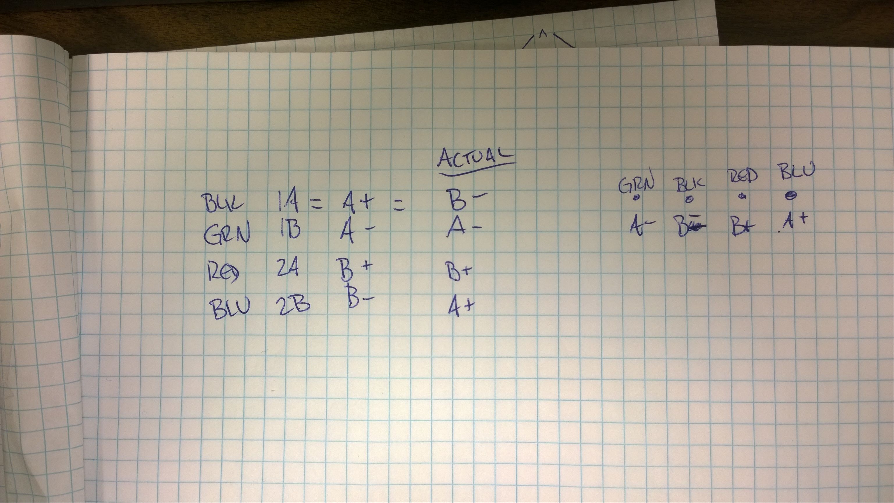
The phases were crossed, and reviewing the schematic for the motor
outputs revealed that I had mixed up the output pins. This is
confusing because of the four different nomenclatures: The
A3967 uses "1A,1B,2A,2B", Wikipedia uses "A+ A- B+ B-", the motor uses
"A B C D", and the actual wires are "BLK, GRN, RED, BLU".
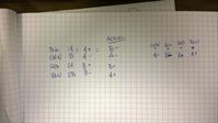
| Motor | Wire | Wikipedia | A3967
|
|---|
| A | BLK | A+ | 1A
|
| C | GRN | A- | 1B
|
| B | RED | B+ | 2A
|
| D | BLU | B- | 2B
|
I reconnected the motor, cranked up the load power to 8.4V/450mA,
and the motor started turning (very slowly)!
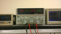
The actual, working wiring configuration:
| Wire | MotorOut | A3967
|
|---|
| GRN | -A | OUT1B
|
| BLK | -B | OUT1A
|
| RED | +B | OUT2A
|
| BLU | +A | OUT2B
|
SUCCESS!
The EZDriver site warns that the driver runs hot, and he wasn't
kidding. Turning very slowly, the driver reached just shy of 200F
and the motor was over 100F. The next version of this board definitely
needs better heat management.
WebV7 (C)2018 nlited | Rendered by tikope in 115.252ms | 216.73.216.220
 I am connecting to a Nema8 bipolar miniature stepper motor
(8HS13-0604S)
. This is a relatively small, strong, and heavy motor. It is not
suitable for any sort of flying aircraft and probably not good
for battery power. But it is common, cheap, and a good representative
of a lot of bipolar stepper motors.
I am connecting to a Nema8 bipolar miniature stepper motor
(8HS13-0604S)
. This is a relatively small, strong, and heavy motor. It is not
suitable for any sort of flying aircraft and probably not good
for battery power. But it is common, cheap, and a good representative
of a lot of bipolar stepper motors.