The intended purpose of this board was to be the simplest MSP430 board that can blink an LED. It was a success. In retrospect, even as simple as it is, it should have been even a bit simpler.
The External/Test power header should be removed; this board will only ever be used in JTAG test mode. MSP430 power should be connected directly to JTAG power. I found myself always needing to solder a jumper wire to select Test power. It would be nice to have an LED hanging off the power line.
I forgot to include GND in TP9. GND should always be included in all header groups. There should always be a dedicated header for GND and VCC to use as oscilloscope test points.
It is easier to solder larger headers than smaller ones; avoid 2-pin headers and jumpers. It is also easier to solder DIP headers than SIP headers. When possible, group pins together into a single 10 or 14 pin DIP header.
There is confusion about the orientation of the parts in the PnP machine. Why were the diodes backwards? Are the caps also in backwards? (For the caps it doesn't matter, but I still want to know.) Do I need to change my DipTrace pattern for all IC's so pin 1 is in the lower left (not upper left) ?
This is my LED pattern:
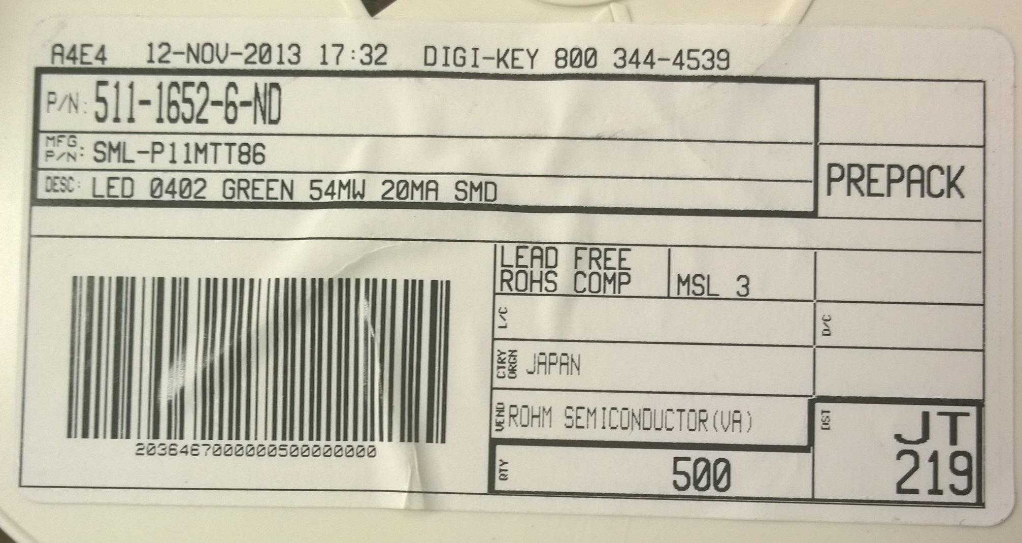
The actual part number from the reel is Digikey 511-1652-6-ND. Looking at the datasheet, the manufacturer's part number is "SML-P11MTT86". The "T86" indicates "cathode at sprocket hole side," which is the LEFT. The cathode is indicated by the diode bar and is connected to ground. My pattern has the cathode on the right, which is why it went in backwards. My pattern needs to be rotated 180 degrees.