TI's forum
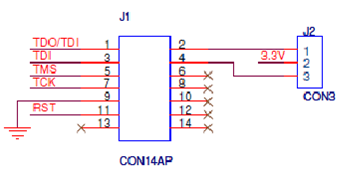
First task is to create the JTAG connector, which will be the connection from the Real World into the MSP430. The JTAG pins:
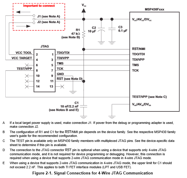
This is detailed in "MSP430 Hardware Tools" page 20. (Checked in under Datasheets/MSP430/)
| Pin | JTAG | MSP430 | Pin |
|---|---|---|---|
| 1 | TDO/TDI | TDO/TDI | 21 |
| 2 | Vcc Tool | Vcc | 23* |
| 3 | TDI | TDI | 20 |
| 4 | Vcc Target | Vcc | 23* |
| 5 | TMS | TMS | 18 |
| 6 | -- | -- | -- |
| 7 | TCK | TCK | 17 |
| 8 | TEST | TEST | 22 |
| 9 | GND | GND | -- |
| 10 | -- | -- | -- |
| 11 | /RST | GND | -- |
| 12 | -- | -- | -- |
| 13 | -- | -- | -- |
| 14 | -- | -- | -- |
*Note: JTAG pins 2 and 4 are routed through a jumper that allows the user to select whether the MSP430 is powered locally or from the JTAG programmer. Connect JTAG:2 to MSP:23 to pull power from the programmer, Connect JTAG:4 to MSP:23 if the MSP430 is self-powered.