April 7 2016
Today's task: Copy the motor controller circuit from JumpMtr to CtrlMtr. This should be much easier than the previous sheets since I will be copying my own design from another DipTrace project. All the components will have been created previously.
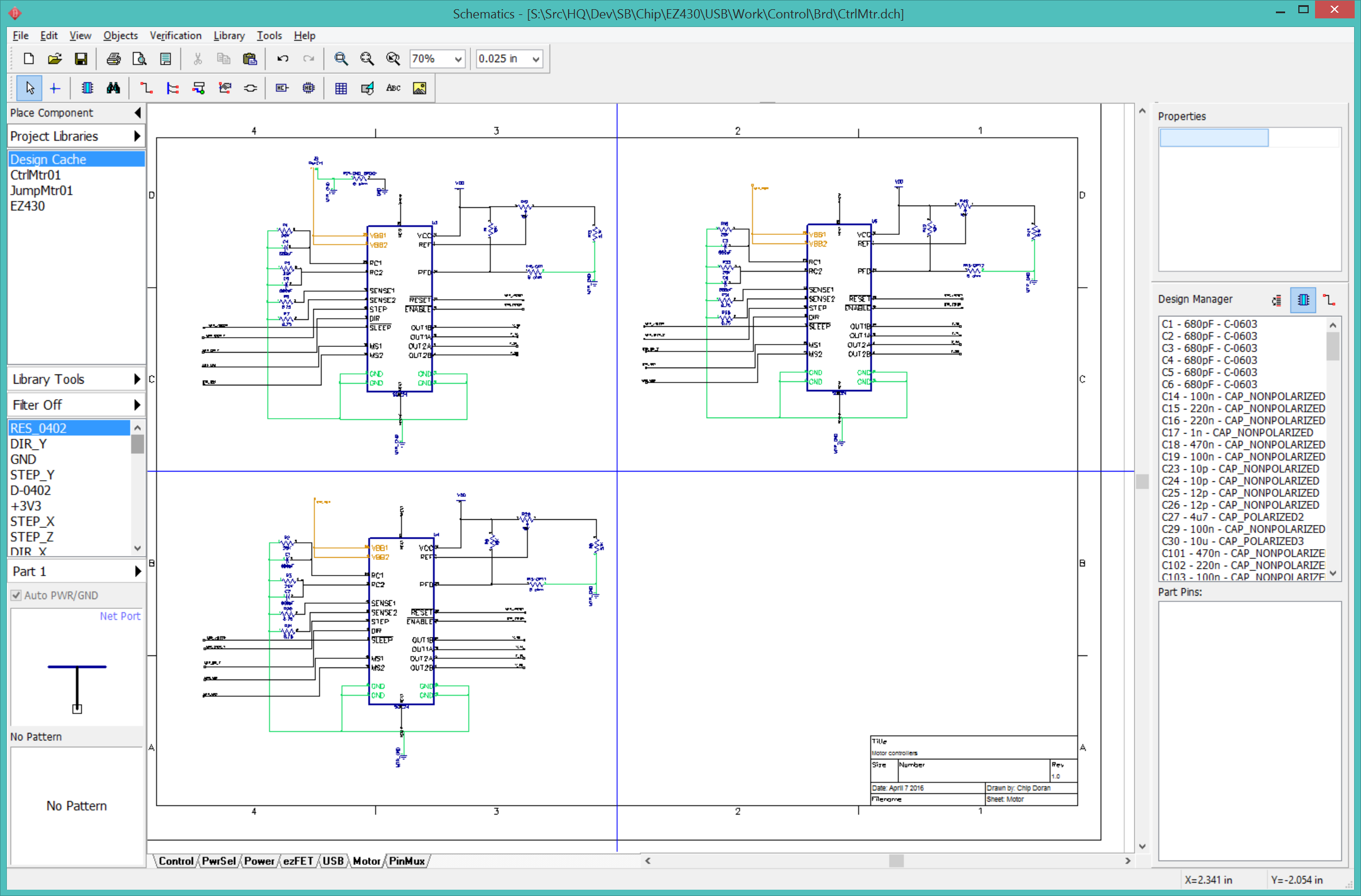
09:00> I copied the U-A3967SLB, J-MTRV2, J-PWR, and R-TC33X2 components from the JumpMtr01 library to CtrlMtr01.
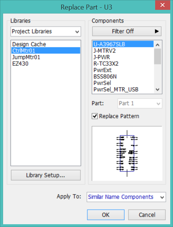
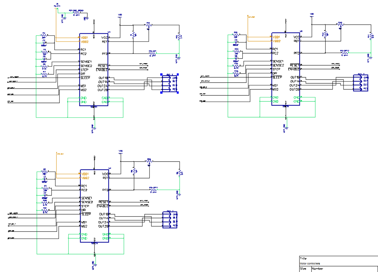
09:02> I copied the X, Y, and Z controllers from the JumpMtr02 schematic into the CtrlMtr/Motor sheet. I am placing all three controllers in the same sheet for this project. The CtrlMtr copy of the JumpMtr schematic still references the JumpMtr component library, I need to "Replace Part" with the version from the CtrlMtr library. Make sure the updated CtrlMtr component library has been saved, then select one of the A3967 components, right-click, "Replace Part...", select the CtrlMtr01 library, select U-A3967SLB, select "Update Pattern", select "Similar named components", and click OK. I can verify that the part now references the CtrlMtr library by opening the component's Properties page and checking the component library path.
09:15> The motor controller schematics have been imported.
The next task is to connect the wires and do some minor rearranging. I want to move the motor terminal blocks to the Power sheet. First, copy the terminal components from the Motor sheet to Power, then delete the terminals from the Power sheet. I need to take care to maintain the proper connections between the A3967 output pins and the terminal pins as this has caused a lot of confusion before. Before deleting the terminal components, first delete the last line segment of the wires. This will leave the wires connected to the A3967 and I won't need to recreate them. Repeat for Y and Z.
April 22 2016
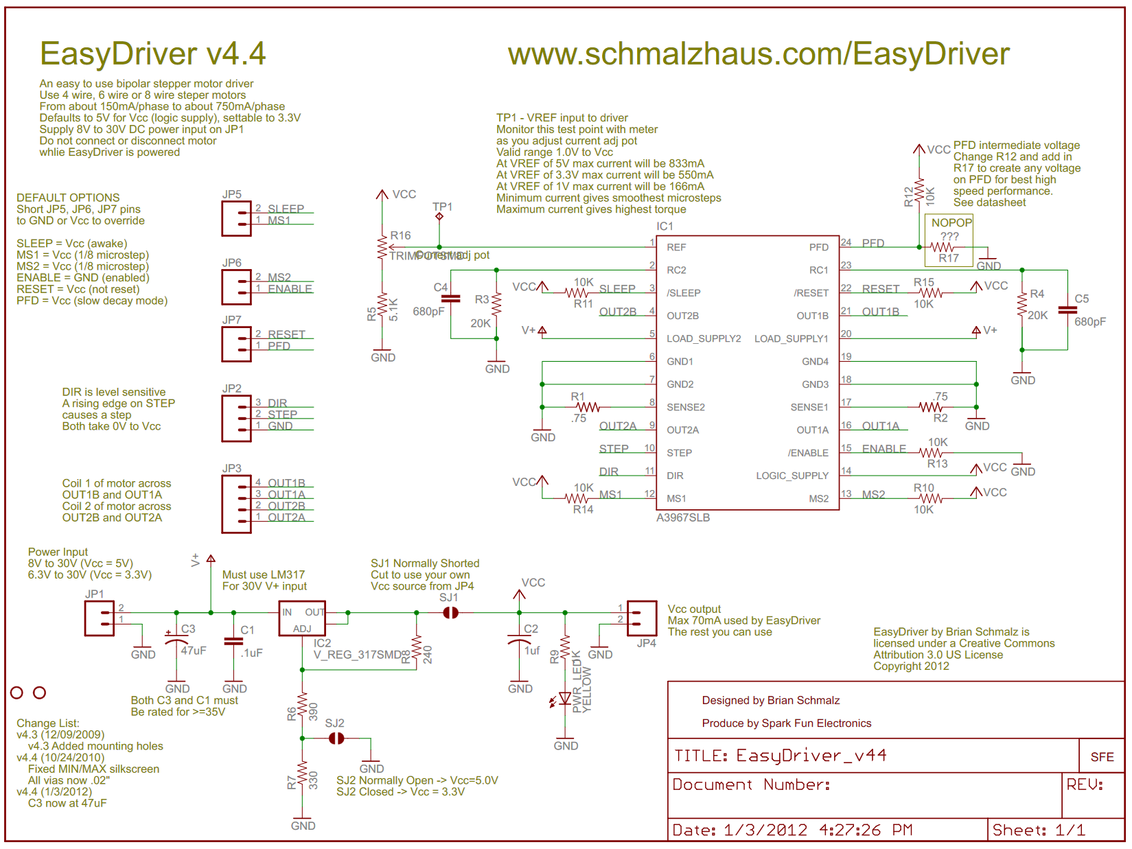
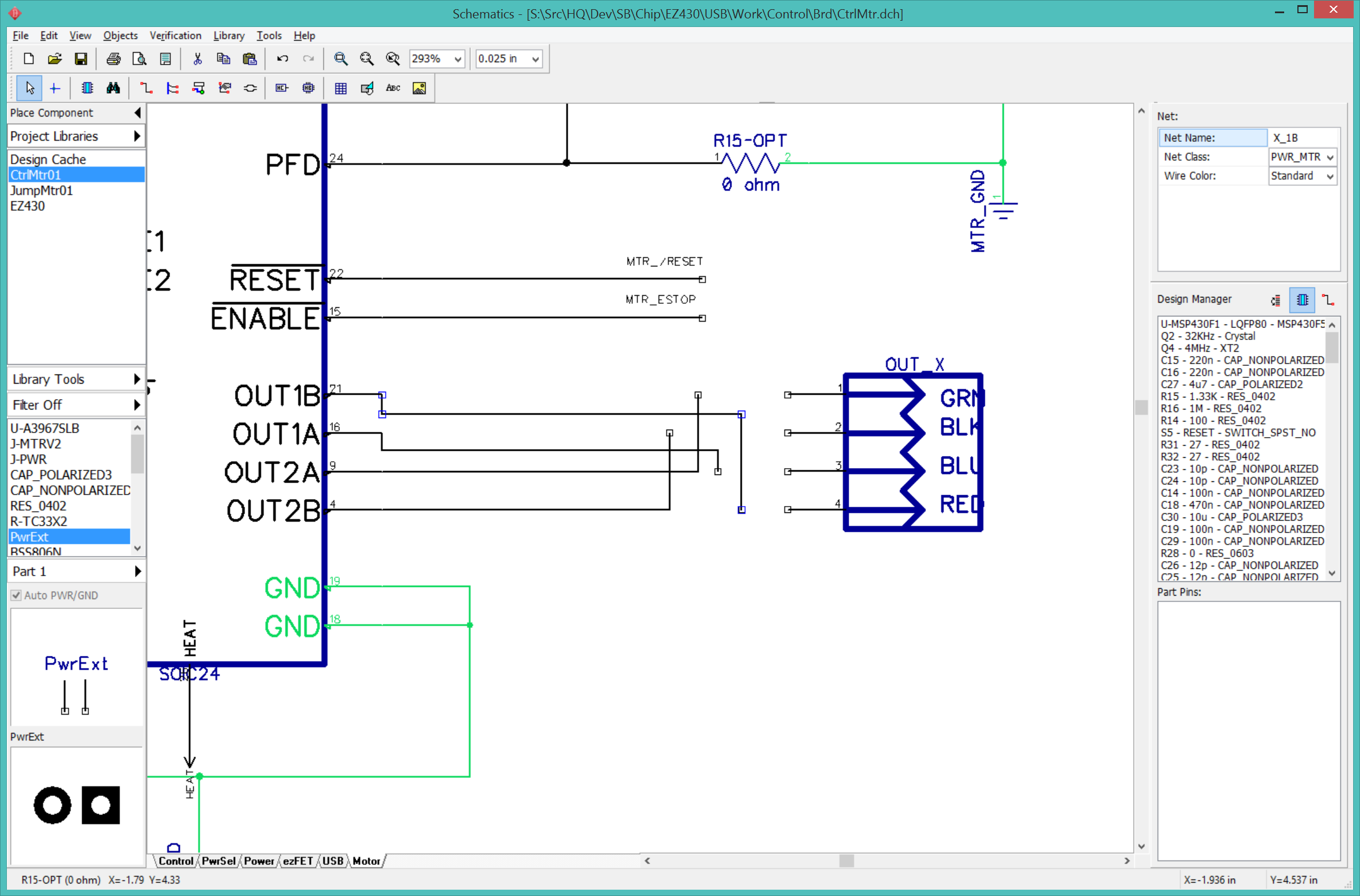
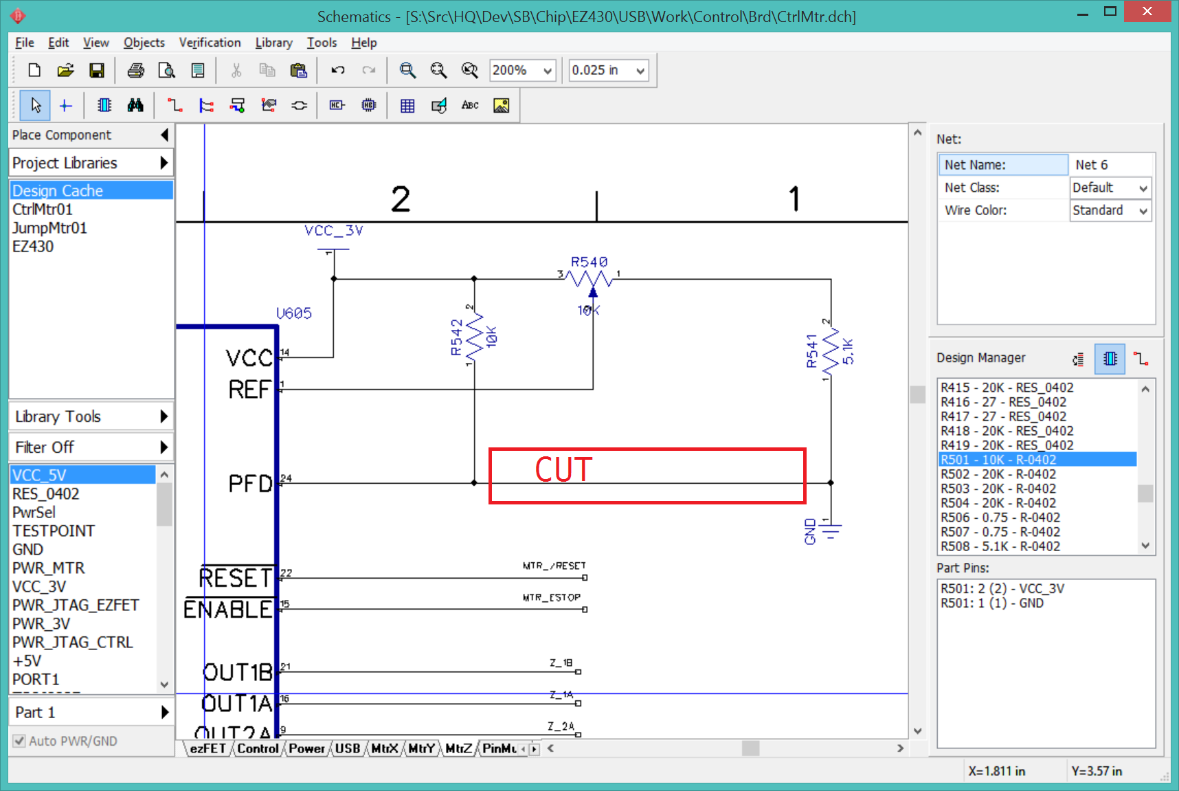
As I was laying out the motor drivers, I noticed that R501 10K is connected directly from VCC to GND. This looks obviously wrong in layout, less so in the schematic where it is intended to provide a reference voltage to PFD. When I referred back to the EasyDriver schematic on SparkFun I found that the design has changed.
A new note was added to the EasyDriver schematic:
TP1 - VREF input to driver
Monitor this test point with meter as you adjust current adj pot
Valid range 1.0V to Vcc
At VREF of 5V max current will be 833mA
At VREF of 3.3V max current will be 550mA
At VREF of 1V max current will be 166mA
Minimum current gives smoothest microsteps
Maximum current gives highest torque
The A3967 datasheet contains this note:
The mixed-decay mode is controlled by the percent fast decay voltage
(Vpfd). If the voltage at the PFD input is greater than 0.6Vcc then
slow-decay mode is selected. If the voltage on the PFD input is less
than 0.21Vcc then fast-decay mode is selected. Mixed decay is between
these two levels.
Should VCC be connected to VCC_3V or VCC_5V? 5V may give better performance. The logic threshold is 0.7V, so either should work. JumpMtr uses 3.3V.
RepRap has a collection of stepper motor drivers and notes on each.
This may explain why my JumpMtr driver was so limited in speed, PFD was shorted to ground when it should be connected to R501.
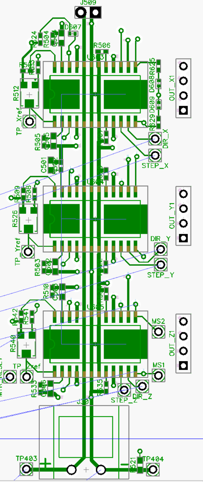
I updated the control connections using the new BRIDGE2 test points, condensed the components around the motor drivers, then moved the three drivers together. The driver circuits measure 3.25x1.25" including the power input and output terminals.