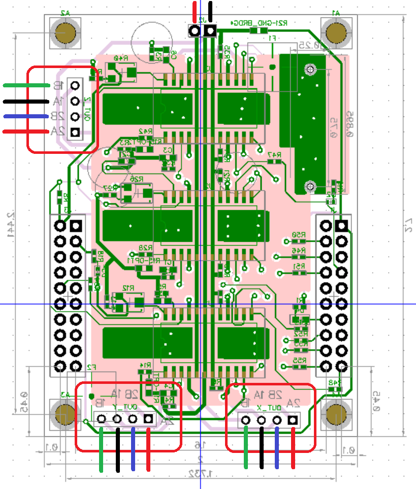
| Pin | A3967 | Coil | NEMA | Wire |
|---|---|---|---|---|
| 1 | OUT2A | +B | B | RED |
| 2 | OUT2B | -B | D | BLUE |
| 3 | OUT1A | +A | A | BLACK |
| 4 | OUT1B | -A | C | GREEN |
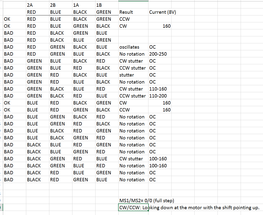
The JumpMtr project paid off today as I used it to verify the stepper motor wiring connections and to figure out why the motor performance is so poor.
First, this is the definitive stepper motor wiring table. With these connections the motor will turn clockwise when DIR is 1 and microstepping works.
|
|
April 26 2016
Testing out the possible wiring combinations. Just to make sure, I tested every possible wiring configuration using my JumpMtr board. The A3967 is running in full step mode (MS1/MS2= 0/0).
The normal wiring also works for half-step mode (MS=01) but quarter and eighth step modes (MS=10,11) stall. I tried all four wiring combinations with no effect. After much anguish I found that the MTR_DIR pin was defaulting to an input, which for unknown reasons causes the quarter and eighth step modes to fail. Setting MTR_DIR as an output brought these microstepping modes to life.
This experiment also confirmed that my motor wiring is correct.
While investigating the microstepping modes, I put the scope on the motor output pins. I expected some motor noise, but the signal is absolutely FUGLY.
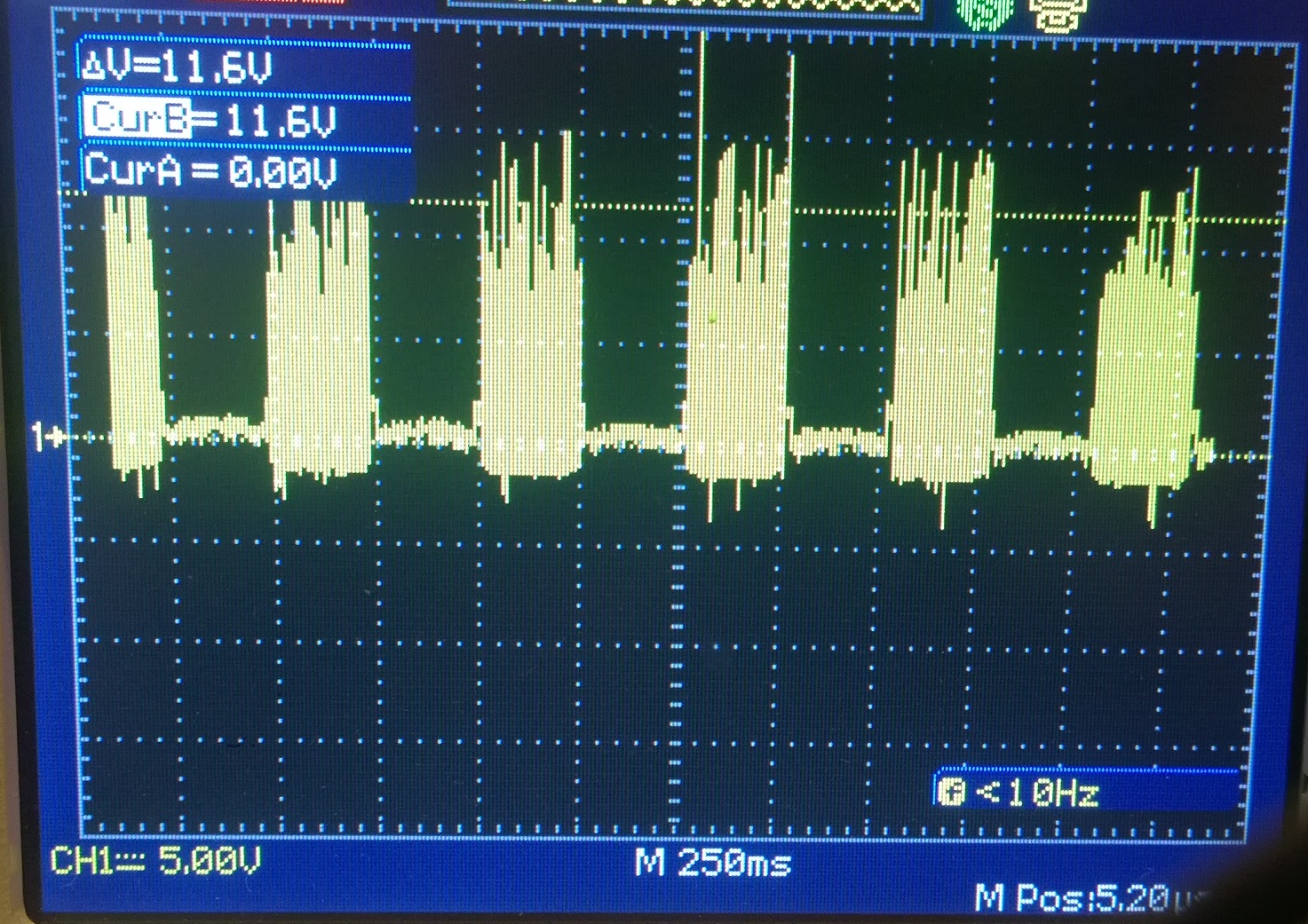
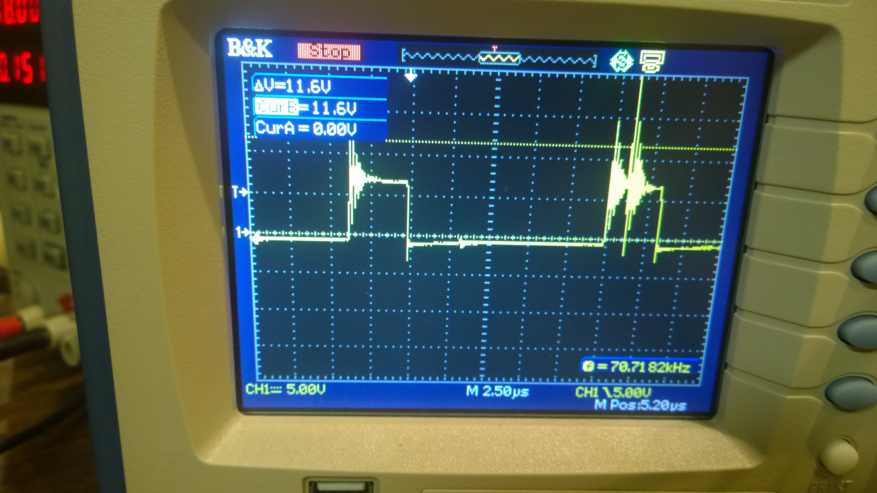
Aha! The MTR power line is fugly because I forgot the big 47uF cap on the motor supply line to smooth out the motor noise! With all the voltage reflections from the motor bouncing straight back into the controllers, its a wonder the signal ever rises above the noise. This explains a lot, including why the motor motion is so glitchy and why it won't run faster than one step every few milliseconds.