Dec 19 2015
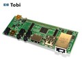
The Tobi board is a good general-purpose IO board for the Overo class COMs. It includes ethernet, USB host, audio in and out, HDMI out. I am mostly interested in the ethernet and USB host.
The Tobi is also simply enough that I can use it as a template for designing my own IO board.
I downloaded
the schematic and layout and saved them locally to
S:\Src\HQ\Dev\SB\Chip\gumstix\overo\tobi\ref\PCB30002-R3564\
I opened the schematic using EagleCAD. My initial impression was that the schematic was clean and well organized. I should be able to copy/paste easily.
The board layout opened in EagleCAD without any problems. It was difficult to determine how many layers were in the board because EagleCAD seems to use the term "layer" to refer to organizational layers, showing 31 layers being used. The board shouldn't be more than 4 physical layers.
After converting the layout from Eagle to DipTrace I'm not sure this layout would be worth salvaging in DipTrace. If I were making a minor change to the existing Tobi layout, it would probably be quicker to learn EagleCAD than to fix it in DipTrace. However, my goal is not to rebuild the Tobi board as-is. The goal is to create and build a stripped-down version of the Tobi that I can then use as the foundation to build it back up into an MSP430-based motor control and sensor board.
The devil is in the details... It did not take long before I ran into the typical lack of detailed information. What the hell is IC7? There is no Bill of Materials included with the schematic! I am forced to try to glean the part numbers by reading the markings on the board.
I found a post about a schematic error with the voltage regulator. I need to make sure it has been fixed in the version I have.