2016-05-20 19:54:52 chip
Page 1703
📢 PUBLIC
May 20 2016
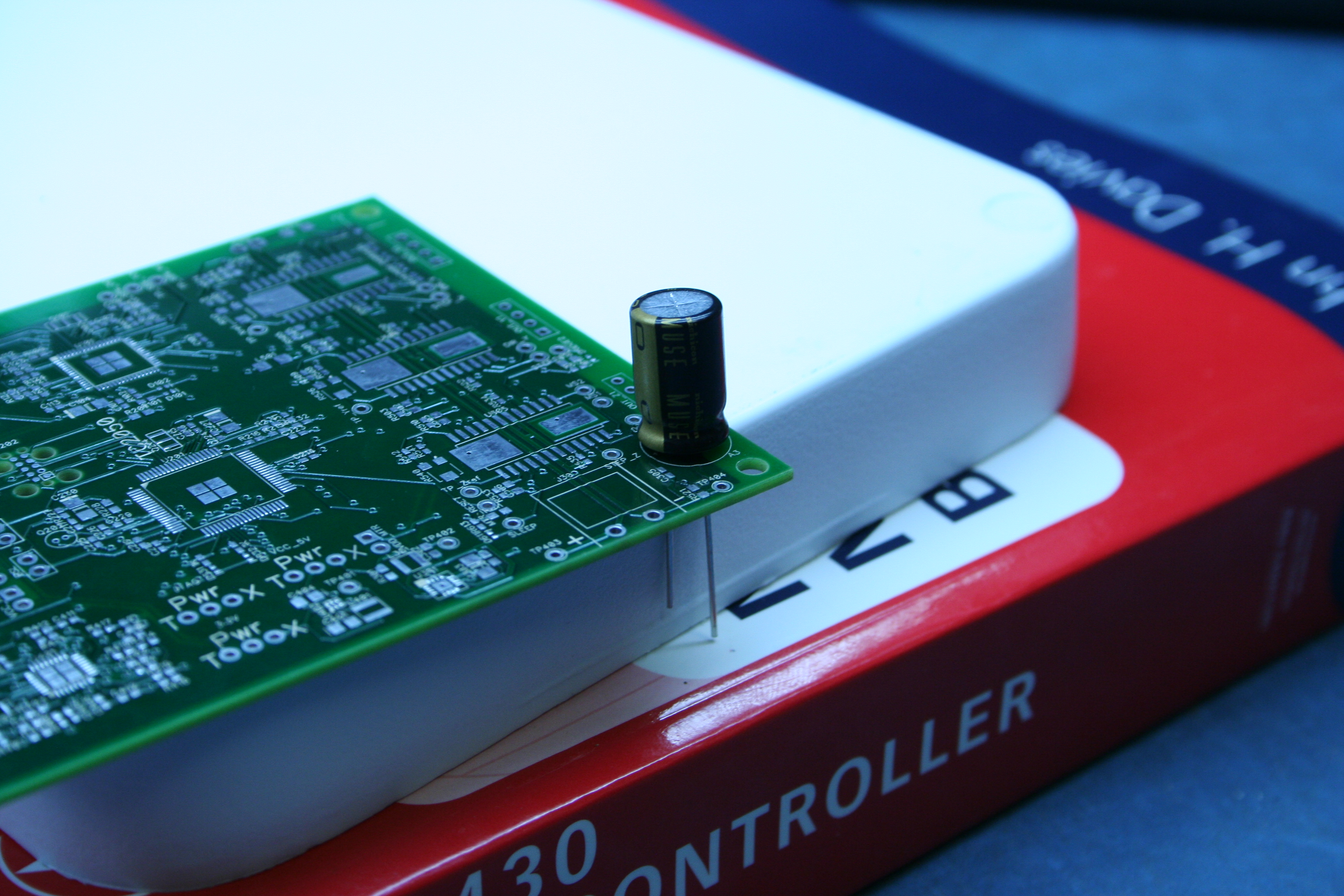
I now have everything I need to build the boards: parts, PCB, and
stencil. I need to preflight the build, then it is time to
manufacture!
Preflight
- Put the solder paste in the warmer, set to 105°F/41C
- Eyeball the stencil on the PCB, make sure everything lines up.
Make sure there are not stencil apertures over the
through-hole pads and JTAG probe pads.
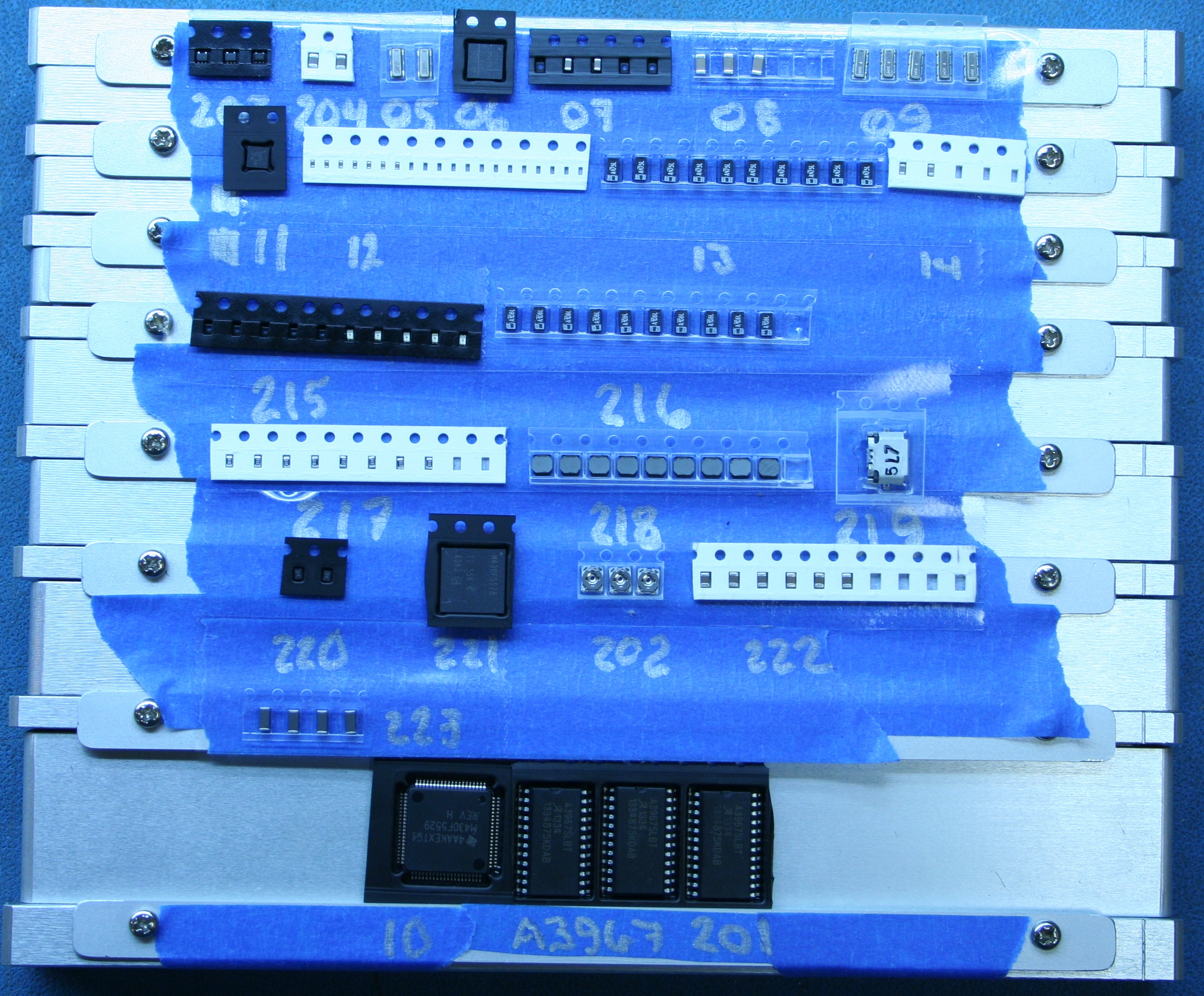
- Reload the tray
Make sure all the parts are oriented correctly.
- Make sure all the parts are loaded in the PnP feeders.
Learn Pick for all the tray components
- Mount the PCB in the machine and learn the fiducials and reference
points.
- Learn PCB
Detect the PCB height using auto-detect, with a
finger on the ESC key. If the machine over-shoots the board,
recalibrate the nozzle 1 open/close suction parameters for both WHITE
and BLACK nozzles. Auto-detection of the board height is very
unreliable, if it fails more than twice abandon it in favor of the
eyeball method.
- Run through the tape pick list
Auto-advance OFF
Learn Pick > Learn all by camera (small camera icon)
Make sure there is a component at the pick location.
- Run through the tray pick list
Print a picture of the loaded
tray to use as a guide. Reset the tray X, Y, and No entries.
Learn by camera each tray component.
Verify the X and Y values
match the actual tray.
- Do a practice pick to verify the tray height.
Select a tray component, click Modify LIB.
- Run through the place list. Production > Vision before production.
- Test the reflow oven.
L302 and L501(Ferrite bead) were a late addition that didn't make
it onto the tray but is present in the component list. I created a new
tray feeder (Q23/223), assigned the feeder to L302 and L501 in the place
list, and un-skipped them.
Q204 is missing from the pick list. This is CAP-0805-1uF which was
moved/merged to Q22/222; 204 was a duplicate of the same
component. FeederID 204 is no longer used.
Build: PnP
- Mount the PCB in the stencil jig.
- Find my paste squeegee.
- Apply solder paste.
- Mount the PCB in the PnP work area.
- Run production.
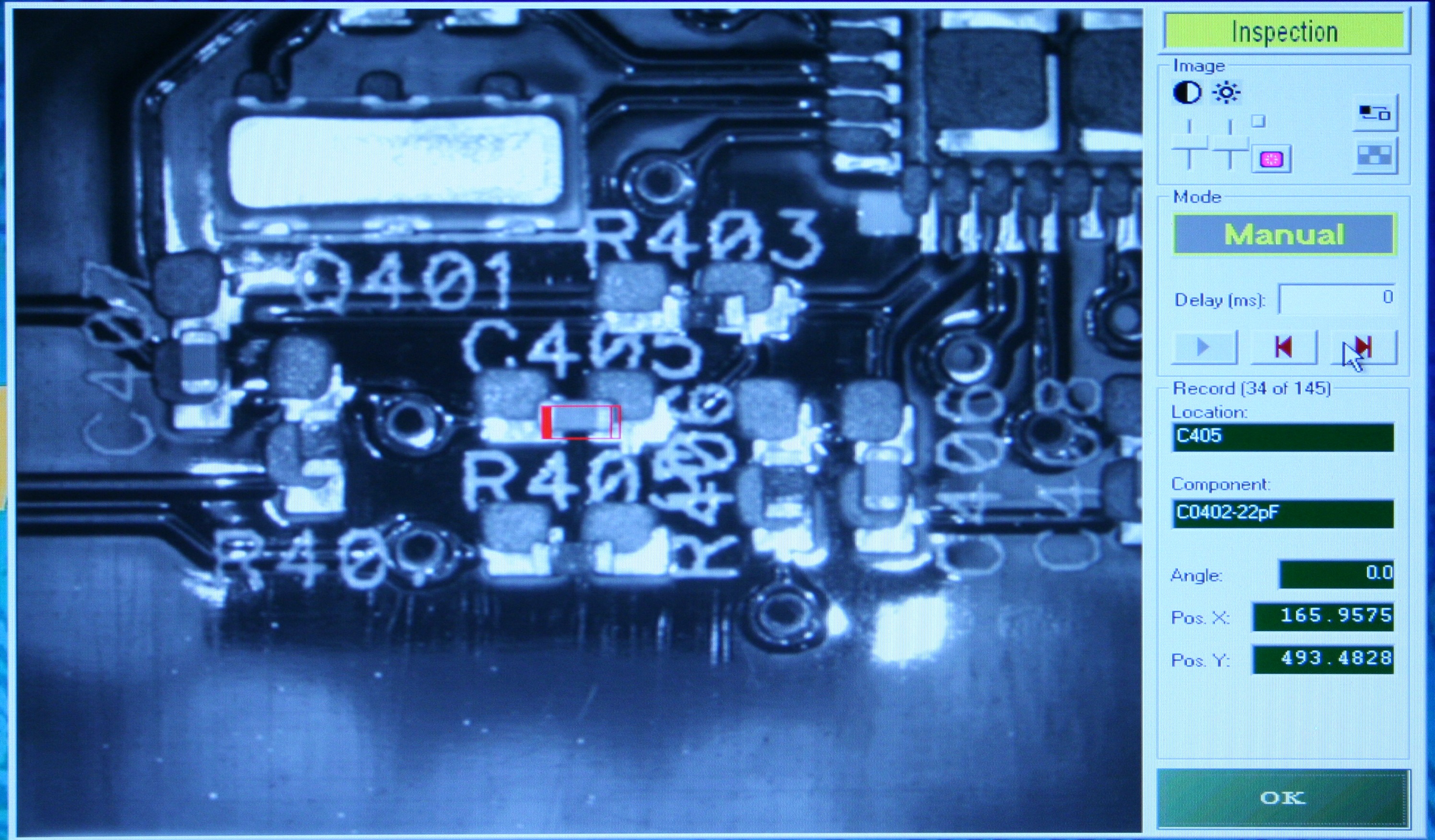
- Visual check: Production > Vision before production
- Mount extra SMT components
L501 (Feeder Q223)
-
- Place the board in the oven.
- Run the reflow profile.
The first production run was epic FAIL. I did not apply the paste
smoothly and there was too much. The bigger problem was that even
though I thought I learned the fiducials (F2,F3) the place was offset
by a wide margin and the machine was dropping pieces outside the
board. I ran the vision check and it lined up, not sure what went
wrong.

Some of my patterns need to be tweaked to make the paste apertures
smaller.

I will clean the board and stencil, reload the tray, and try again.
The paste can be removed by gently wiping with cotton balls
lightly soaked with rubbing alcohol. Take extreme care not to wrinkle
the stencil during cleaning. Always wipe away from the held edge,
never back. Thoroughly clean my hands afterward, do not leave solder
paste on the skin or it will begin absorbing the lead.
The second run was on target, but the results were very poor, with
16 missing or bounced components. I believe the problem was not in the
pick or place, but in the "stick" to the board. Nor is the problem due
to too much paste, which helps the parts to stick better but then
causes bridges during reflow.
I think three things went wrong:
- I applied the paste before I verified the tray picks and
re-learned the fiducials and reference points. This let the paste
dry out (oxidize?) and lose some of its tackiness.
- The board was poorly secured to the work area. I was still
using the 4 posts to support the board with one post too short.
This allowed the board to bounce when placing components near
the short support. This configuration was left over from the
paper board, where the laminated boards were too thick for the
edge clamp. I need to remove the two posts, resume using the
edge clamp, and re-learn the board height.
- Less likely, but still a possibility, is that the paste
is too old and is not working well. This is my original tub
from 2012 and has not been stored well. I will open up my
fresh jar for the next run.
Since this build ran to completion, an entire board was consumed
from the tray. I recovered the major components. I hope the paste that
is still adhering to the legs does not create more problems.
The paste apertures are definitely too large. I need to go back
and review the patterns.
0402 resistors and caps are definitely too small, much more trouble than
they are worth. All future designs should use 0603 (or larger) unless
there is a compelling reason to go smaller. I can handle 0402,
but everything has to be just right -- most importantly the
paste apertures in the stencil. For tiny parts, the apertures need
to be even smaller than the pads.
I need to reset the tray, reload the depleted components from
stock, clean the stencil, board, and squeegee, and try again.
It is now 1950, time to take a break for dinner. It appears the
build will extend to a second day. :(
May 21, 14:40
I need to refill some of the tray components:
- 207: CAP-0603-22uF, 1276-2867-1-ND, Qty 2
- 212: CAP-0402-220nF, 445-4972-1-ND, Qty 8
- 214: CAP-0603-3300pF, 1276-2275-1-ND, Qty 2
I need to order more 220nF caps, preferrably upgrading to 0603
(Digikey 1276-1112-1-ND).
I ran out of D13, D-0402-GRN, the green leds. I have some 0402
yellow leds I can use.
The fresh paste seemed to apply to the board better. The auto build
went well until it failed to recognize some of the larger tray
components. I think it was being fooled bits of leftover paste on the
undersides, which I will need to clean. I skipped these and continued.
😬
Then Autotronik hung in mid-stroke. The application locked up and I
had to Ctrl-Alt-Del to kill the process and restart. This is the first
time I have experienced an application hang during a production
run.
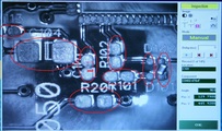
Reviewing the partially built board, good news and bad news. Good
news: the parts that were well placed and stuck. Bad news: I was a bit
off with the paste, and the lower left corner was bad -- the board
would have failed QA even without the crash.

This is progress. I will need to clean, reset, restock, and restart
-- for the third time.
I spent quite a bit of time wiping solder paste off even the tiniest
of parts... I'm looking at you, TPS62237! (Note to self: TPS62237 is
for use in watches and nanomotors). I restocked the tray and swapped
the empty green led autofeeder for yellows.
The thorough cleaning created a different problem, 4 parts stuck to
their compartments and the machine was unable to pick them. I
reshuffled them and they worked on the second pass. The pick height on
the yellow leds was off and required a third run. For some unknown
reason, L301 was missing and not present in the error list. I created
a place list with just that part and it placed.
1910> With a lot of help, the third run made it to the finish line.
The visual check looked good, all the parts were present and in good
shape. I am more concerned about the amount and position of the paste.
I am praying to the Wicking Gods that the solder sorts itself out in
the oven...
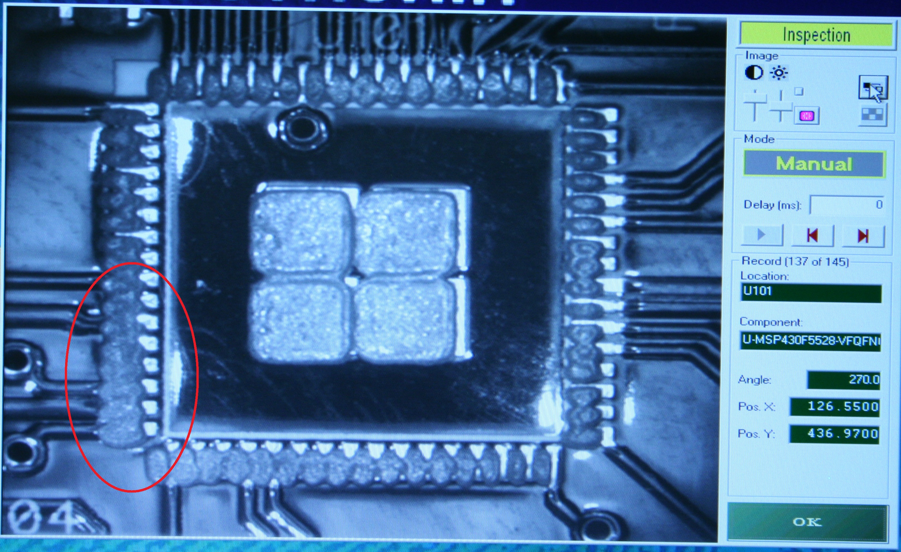
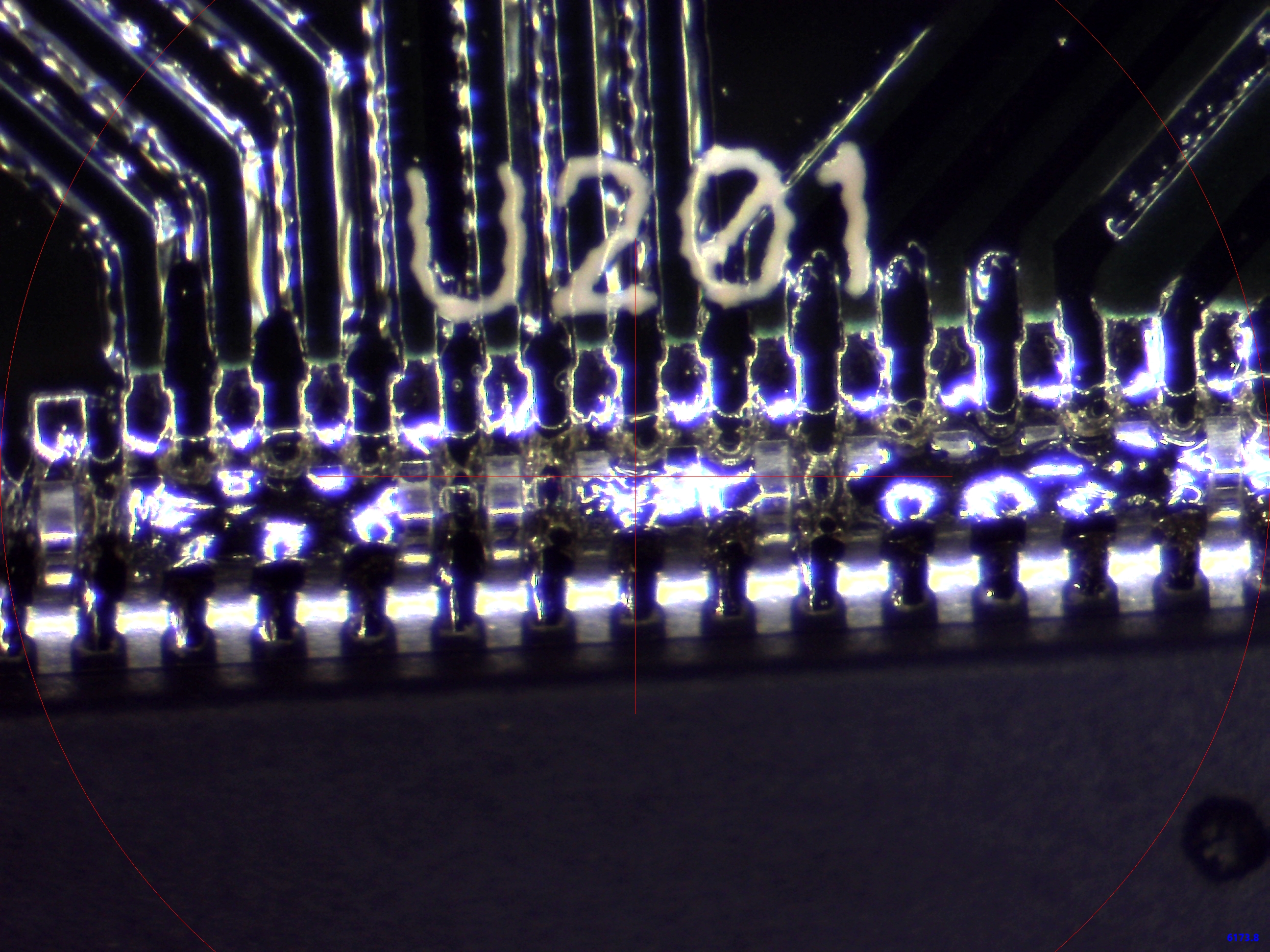
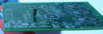
2000> The board looks good out of the oven, PnP visual inspection
shows the components have centered themselves. I am worried about shorts,
especially between the pins of the MSP430.
Build: Hand Solder
- 7 2-Post headers:
J509, VDD-MTR, BSL, RESET, VCC-HUB, VCC-EZFET,CTRL-3V
- 3 3-Post headers:
Pwr:JTAG, Pwr:VCC-5V, Pwr:3.3V
- 3 4-Wire leads:
OUT-X1, OUT-Y1, OUT-Z1
- 1 Terminal block:
J301
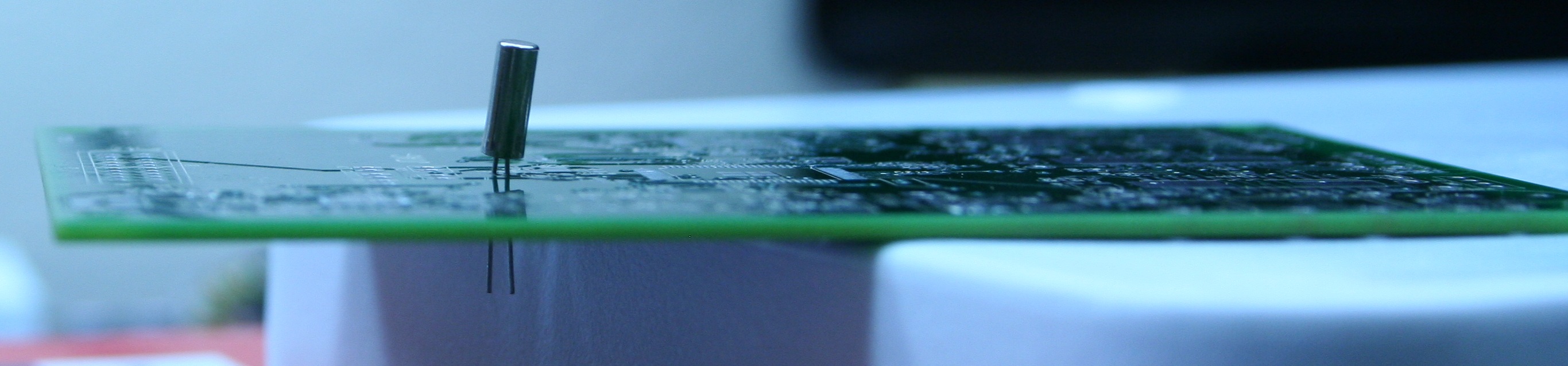
- Q202(32KHz crystal
The crystal is not polarized, either way is OK.

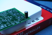
- C304(100uF radial cap)
Square pad is ground (short leg), round pad is positive (long leg)
- 1 20-Post headers:
J641
Test
2115> I found the old MSP430-FET430UIF and the TagConnect adapter,
plugged it in... "Unknown device". This is the message when the MSP
fails to respond to the FET. I looked at the MSP430 under the scope
and it looks like the legs are all fused together into one giant
solder ball.

I have to write off this board and everything on it. This is about
$30 in parts, $35 for the stencil, and another 2 days of layout and 4
days for the new stencil to arrive. This is demoralizing, but it is
progress. The fresh solder paste made a huge difference, I believe I
could place all the parts in a single run next time. The big mistake
was the stencil: I failed to check the shrink on the solder paste
apertures, especially for the MSP430s. This is the second time
() I have learned this lesson the hard way.
I wrote up a guide for setting the paste shrink: .
The problem is in the stencil, not the boards, so I can continue to
build with the remaining 3 boards and a new stencil. I must create the
new stencil from the archived layout for the 20160511 boards, editing
a new copy of the archived layout, and using the "expedient"
method of tweaking the pads directly in the layout. I cannot
regenerate the board from the schematic, as I have made changes to it
since ordering the boards.
WebV7 (C)2018 nlited | Rendered by tikope in 115.209ms | 216.73.216.220