April 6 2016
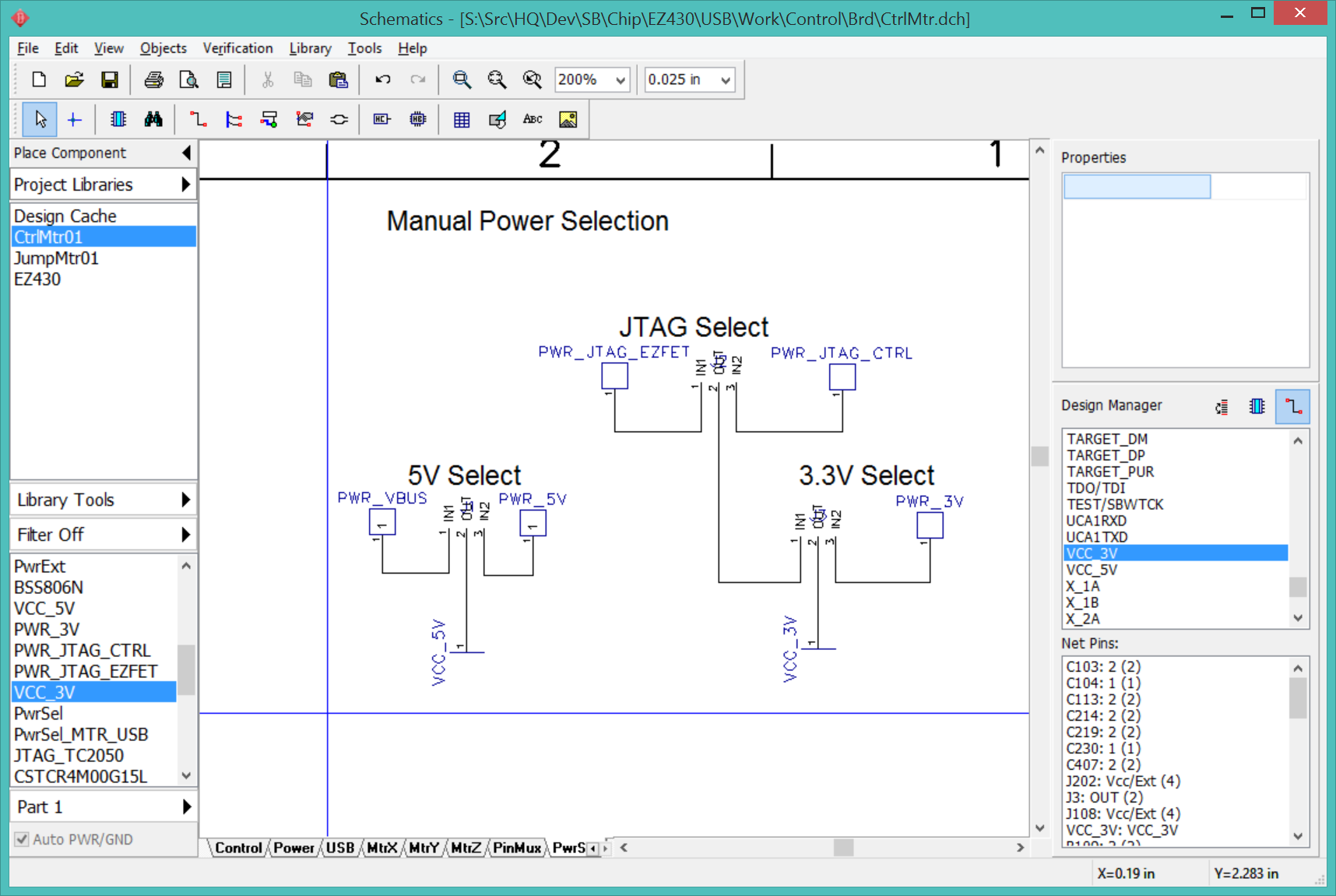
The power selector circuit has become complicated enough to warrant its own schematic sheet.
CtrlMtr has 4 power sources:
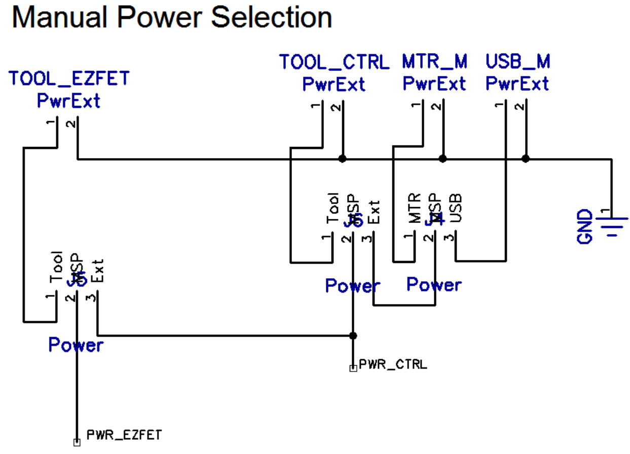
The question is: Do I need to provide a set of jumpers to select the power source, or can I hard-wire the power source based on preference and availability? The order of preference would be:
If I use jumpers to manually select the power the jumpers must always be present. I can still leave the MTR power converter hard-wired to ON, it just won't be used.

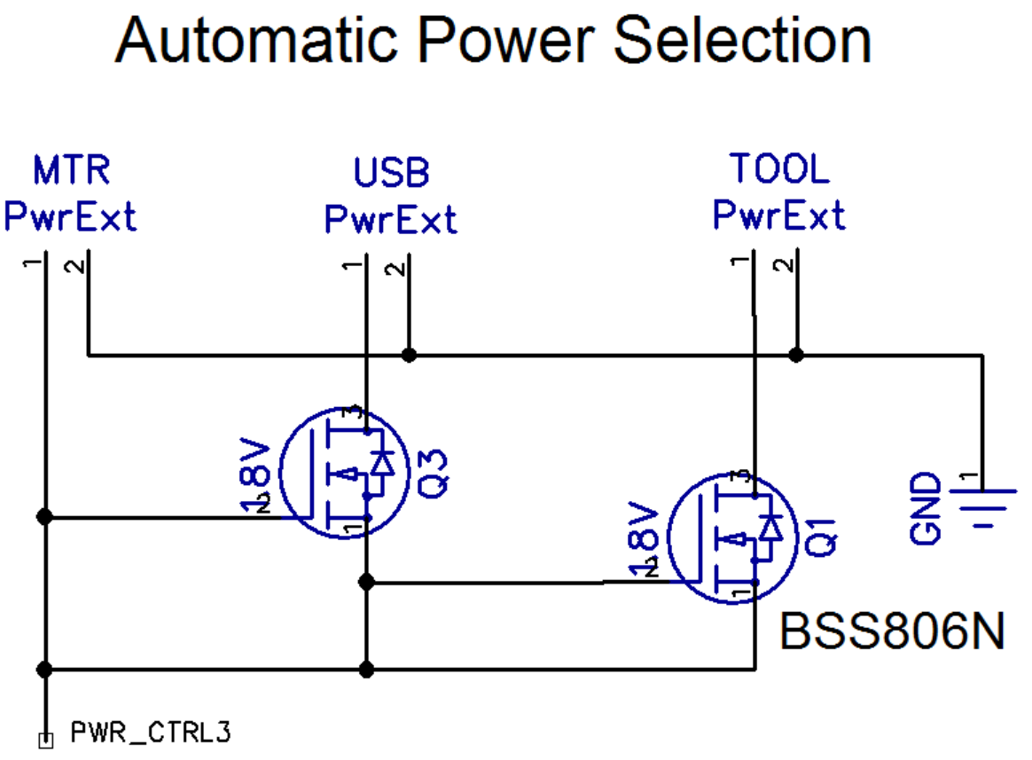
If I automatically choose the power source, PWR_MTR is the first preference and I can hard-wire ON/OFF to ON. I then use transistor switches to control the PWR_TOOL and PWR_USB sources. Electronics-Tutorials.ws has a good explanation of the types of MOSFETs and their symbols.
The problem is that I want the transistors to be normally ON, turned OFF if the power source to the left is on. These transistors (Infineon BSS806N) are normally off. I believe this means I want a "depletion mode" n-channel mosfet transistor, but those don't seem to exist. What part should I be using?
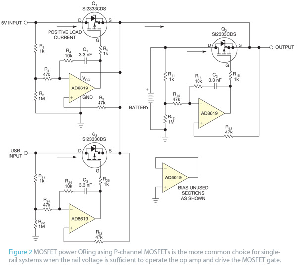
Bruce pointed me to this article that looks like it does what I need, at the cost of losing a few millivolts. He also suggested a single TI part (TPS2114A, Digikey 296-16939-1-ND) that does everything, but for only 2 power sources; I would need a pair to handle 3 sources. It is a bit expensive at $1.87 (in 100's).
April 17 2016
The power inputs and nets need to be reworked. There are 6 power sources on the board, all the outputs from these sources are PWR_ nets and inputs to the PwrSel switches.
The JTAG connectors also have pin 4 connected to the board Vcc, which acts as a drain in the case where the board has its own power supply. TODO: Check that JTAG:2 and JTAG:4 are never shorted together.
The PwrSel contains a set of 3-post headers that are used to select the various power sources. The inputs are the various PWR_ nets and the outputs are the VCC_3V and VCC_5V nets. There is no need for a VCC_12V net since the only source for 12V is PWR_MTR.
VCC_5V and VCC_3V are the nets that should be used to power all the digital components, including the MSP's and A3967 Vdd inputs.
Renaming wires and nets is tricky. The same wire may appear in multiple places and multiple sheets and DipTrace will apply the name change to all instances. Checking the "Apply to related wires only" will isolate the change to just the current wire and not the entire net, but again that wire may span multiple sheets. DipTrace may refuse to change the net name when the wire is connected to multiple components. In these cases I may need to delete the wire completely, add a wire stub to one of the components, rename the net, and then connect the other components. I always need to proofread the schematic after renaming nets to catch wires that were unexpectedly changed.
It works to simply leave wires dangling and rely on common net names to tie them together, but this leaves the schematic looking unfinished. I would rather terminate the wire with a net port both to make the off-sheet connection more obvious and to signal that the connection is complete. Using net ports requires that all ports with the same name have the same pin names, otherwise DipTrace complains when I try to place the new port. The pin does not need to match the net name, although it eliminates confusion if they are the same. The naming confusion is minimized by creating a new copy of the stock net port in the project component library and setting the port and pin names to the name of the net used in the schematic. Create a new port in the project component library that is specific to the net. This will save me from accidentally renaming every net connected to "PORT1".
If DipTrace complains about misnamed pins when I try to place a net port, it is probably because I have ports with the same name that still refer to the stock component library. I can track them down using the Design manager.
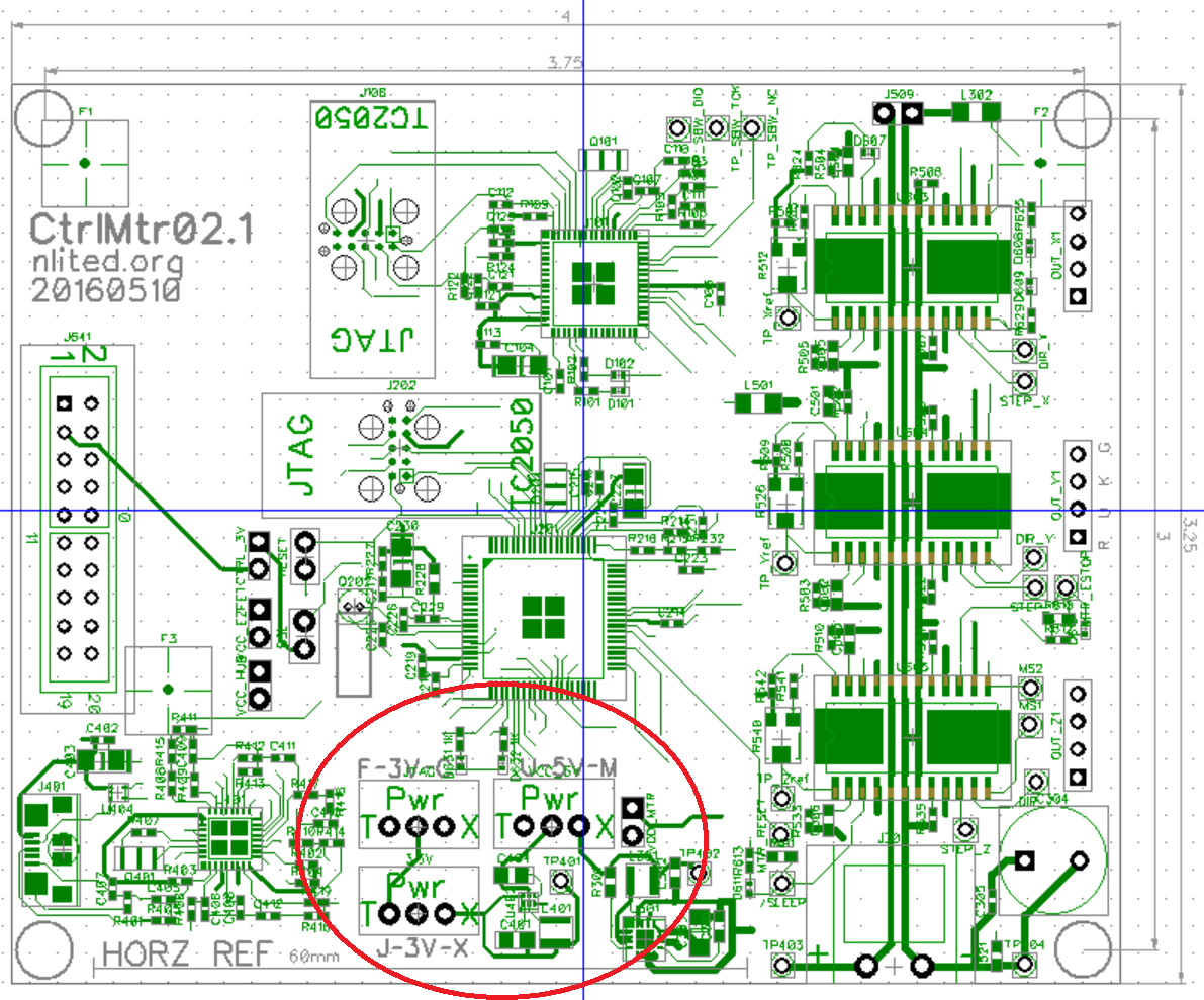
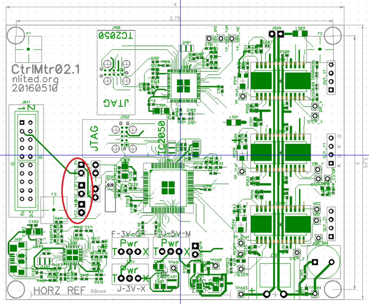
Here are the revised sheets after renaming all the PWR_ and VCC_ nets.
The power selectors allow the board to run in several power configurations. Normal mode powers the everything from the MTR power. The USB hub is active but the VBUS power is not used. Test mode disables the motors and powers the microcontrollers from the USB power bus. FET1 powers only the 3.3V rail from the JTAG programming tool through the Tag-Connect interface J202. FET2 powers only the 3.3V rail from the JTAG programming tool through the Tag-Connect interface J108.
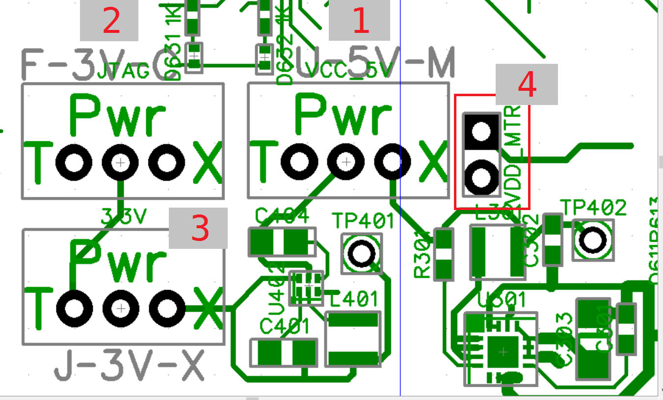
| Mode | 1:U-5V-M | 2:F-3V-C | 3:3.3V | 4:VDD_MTR |
|---|---|---|---|---|
| Normal | 5V-M | X | 3V-X | VDD_MTR |
| Test | U-5V | X | 3V-X | -- |
| FET1 | -- | 3V-C | J-3V | -- |
| FET2 | -- | F-3V | J-3V | -- |
The VCC_HUB, VCC_EZFET, and CTRL_3V jumpers must be in place to power the USB hub, MSP430F5528, and MSP430F5529 respectively. They can be removed to de-power individual components while using the JTAG programming tool.
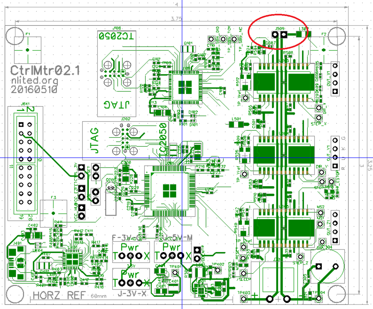
J509 is connected directly to the MTR power rail and can be used to daisy-chain additional devices.