April 5 2016
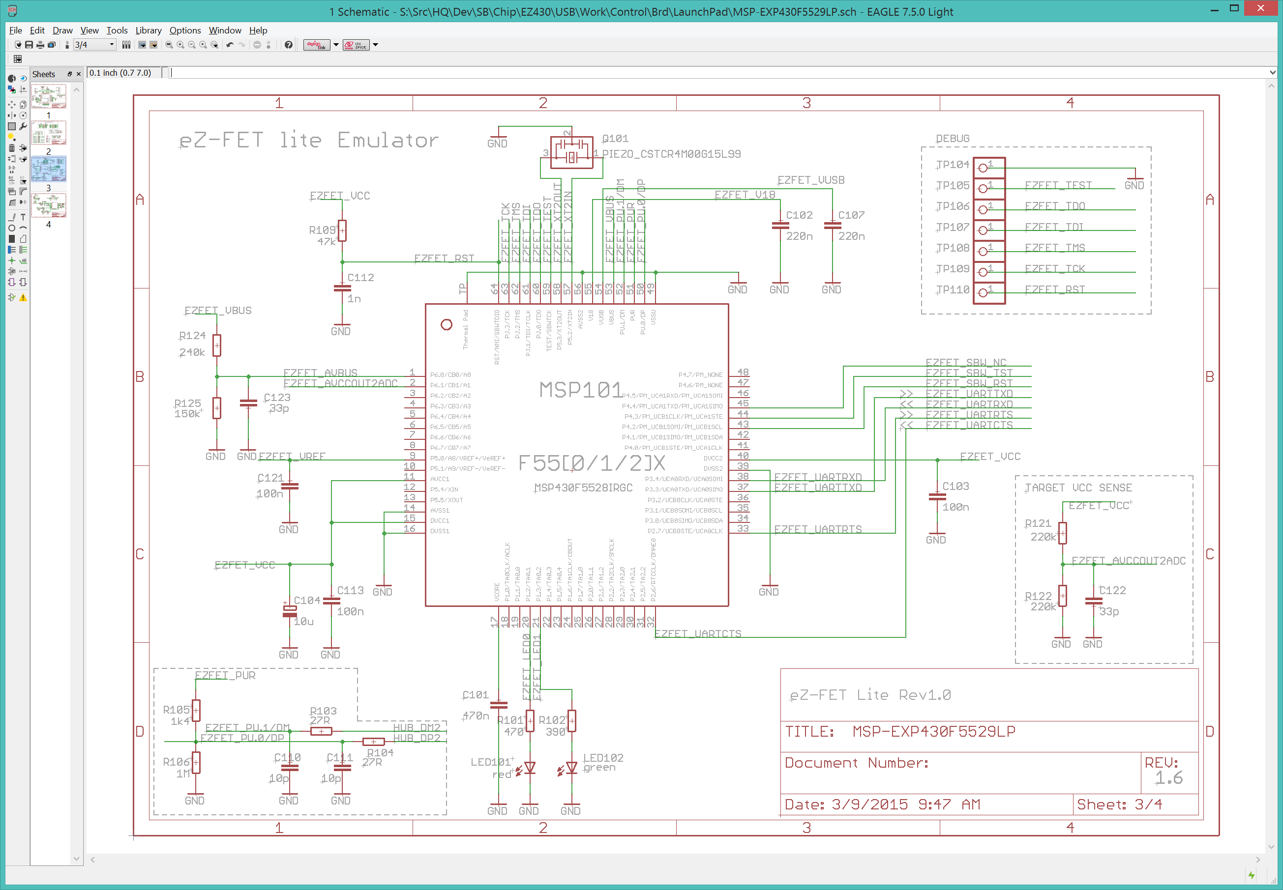
Today's task is to copy the ezFET interface from the LaunchPad schematic into my CtrlMtr project.
Why do I need another MSP430? The MSP430F5529 is functionally identical to the MSP430F5528 except that it is in a slightly smaller 64-pin package vs the 5528's 80-pin LQFN. The reason is software. The 5529 will be flashed (once) with the ezFET firmware and never changed. The ezFET firmware will manage the USB hub, advertise the two serial devices (the ezFET programmer and the serial link to the UART on the 5529), and handle all the FET programming commands to rewrite the firmware on the target 5528. The 5528 might have the firmware to support USB operations, but it is not required. The 5529's role is to always be running, even while reprogramming the board (meaning the 5528). This frees up the 5528 to be dedicated to running just the motor controller code. The alternative is to use an external USB FET connected to the JTAG pins, which is precisely what I am trying to eliminate.
Launch EagleCAD, open the LaunchPad schematic, and select the ezFET sheet.
16:40> Open the CtrlMtr schematic and create a new "ezFET" sheet. The first task is to create the MSP430F5528 component. Open the MSP430F5528 datasheet to the pin diagram (Figure 4-2).
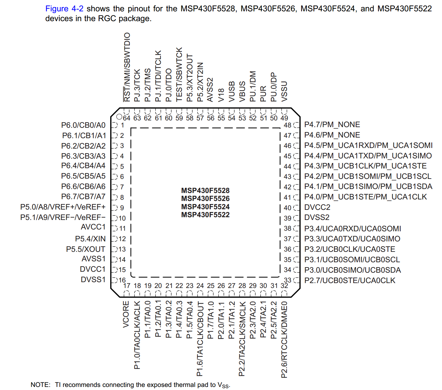
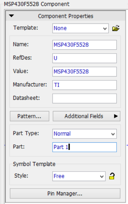
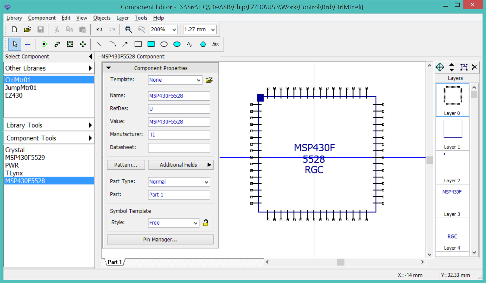
Create the 5528 component. The MSP430F5528 is functionally equivalent to the MSP430F5529, except that the '28 is a 64-pin RGC package and the '29 is a 80-pin LQVFN package. Launch DipTrace Component Editor, open the CtrlMtr library, Create a new component.
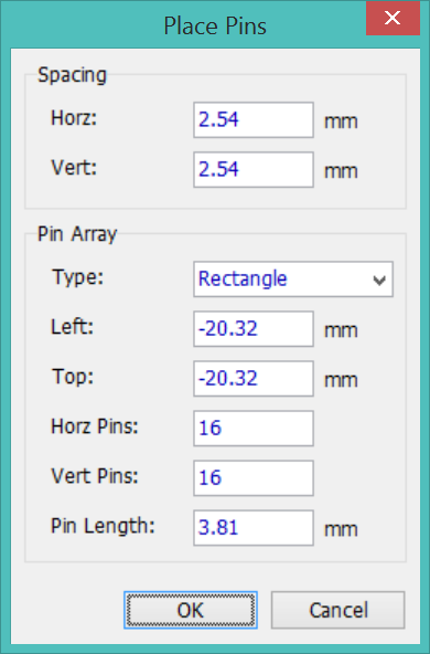
This is a 64-pin RGC device, 16 pins in a rectangle. Select Menu > Objects > Precise Pin Placement. Select a rectangle pin array. Leave the spacing as 2.54mm (0.10"). Left and Top are -2.54*(16/2)= -20.32. Set the pin count to 16 and 16. Add shapes to outline the component and to indicate pin1. I find it helps if the body outline slightly overlaps the ends of the pins, this prevents the shape from interfering with the text of the pin names.
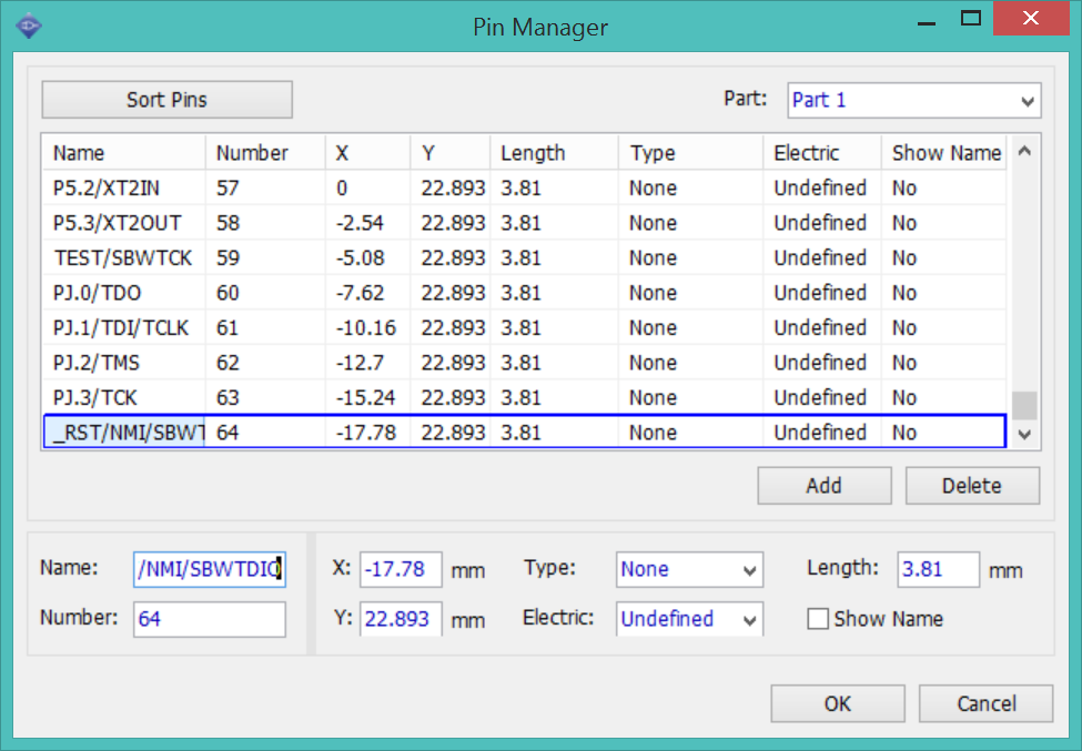
17:15> Open the pin manager and enter the pin names.
17:24> Done. Save the component and drop it into the ezFET schematic.
Open the CtrlMtr BOM spreadsheet and the LaunchPad BOM. Add all the support circuitry, adding new parts to the BOM.
C104 Digikey 493-2351-1-ND is no longer available, replaced with 718-1118-1-ND.
LED101 and LED102: Replaced with the same leds used in JumpMtr.
R102: I replaced the 390ohm resistor with 470ohm to reduce the part count. This is the attenuation resistor for the green led.
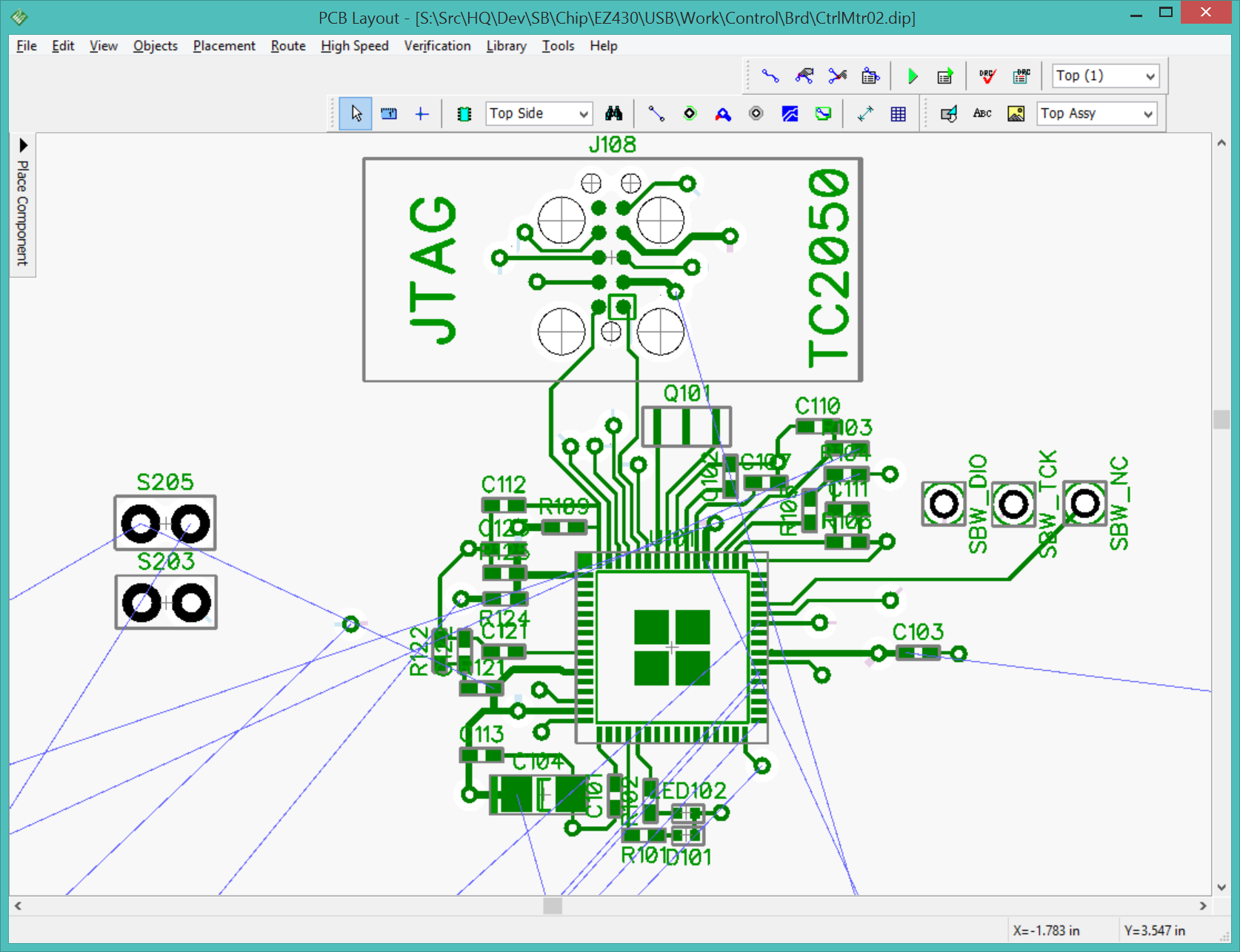
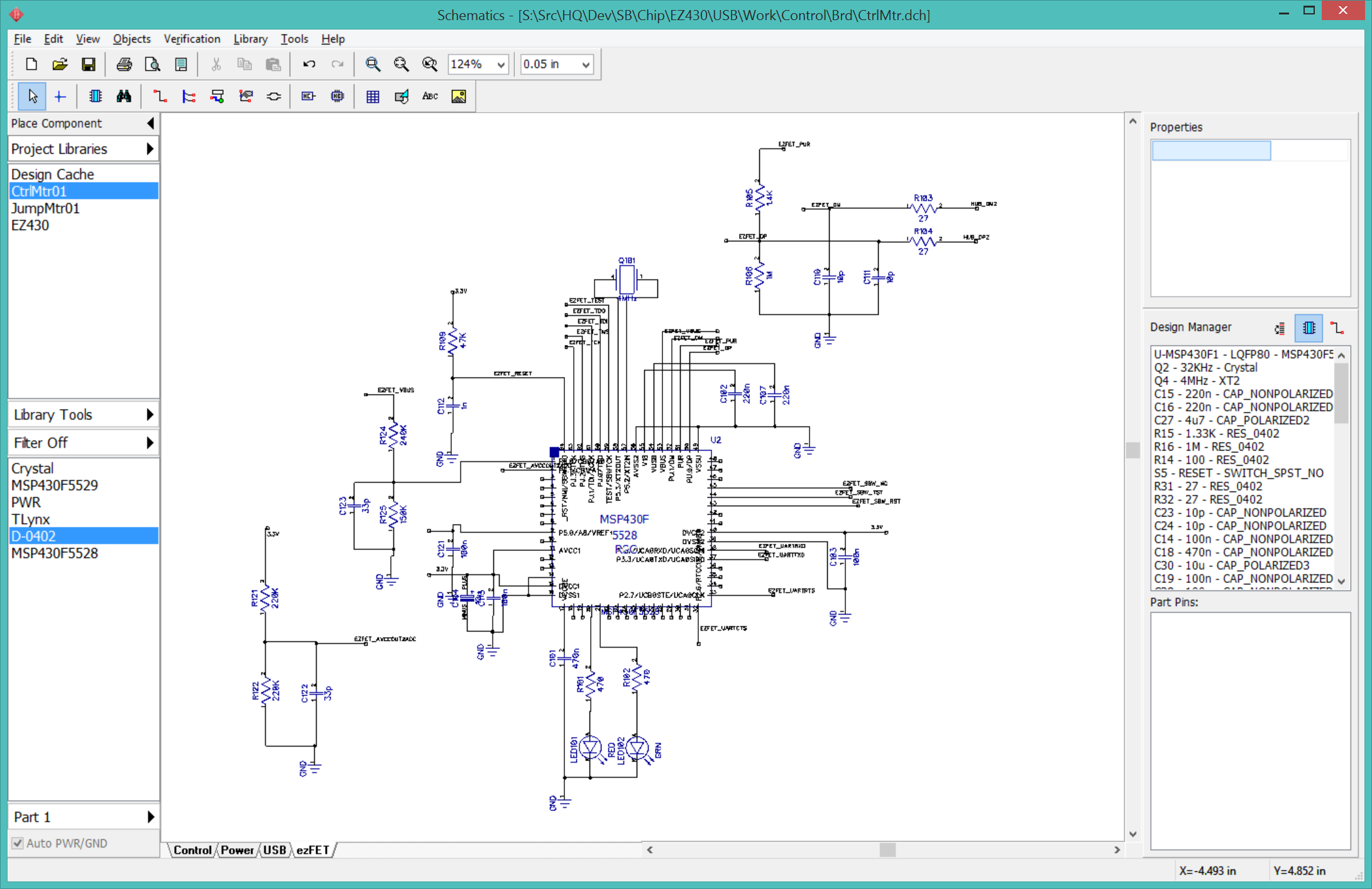
19:37> I have the first rough draft of the ezFET circuit.
I need a JTAG header so I can bootstrap the firmware on the ezFET. I will use a TagConnect header for this. 43oh.com has a forum thread discussing designing an ezFET-Lite clone. I suspect programming the 5528 may turn out to the be most difficult part of this circuit. TI MSP Debug Stack. This page discusses exactly this problem.
April 6 2016
I cleaned up the ezFET sheet a bit and added the TagConnect interface for the 5528.
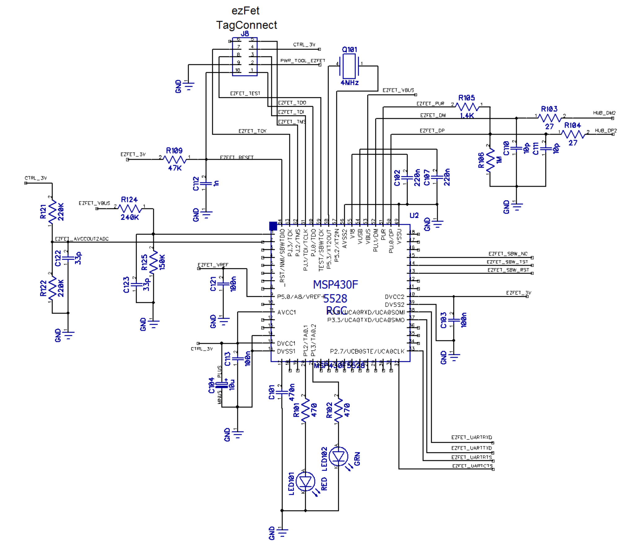
Replaced R105 1.4K with 1.5K.
Replaced R121, R122 220K with 240K.
EZFET_V18 (5528:V18:55) is only connected to C102.
EZFET_VREF (5528:VeREF+:9) is only connected to C121.
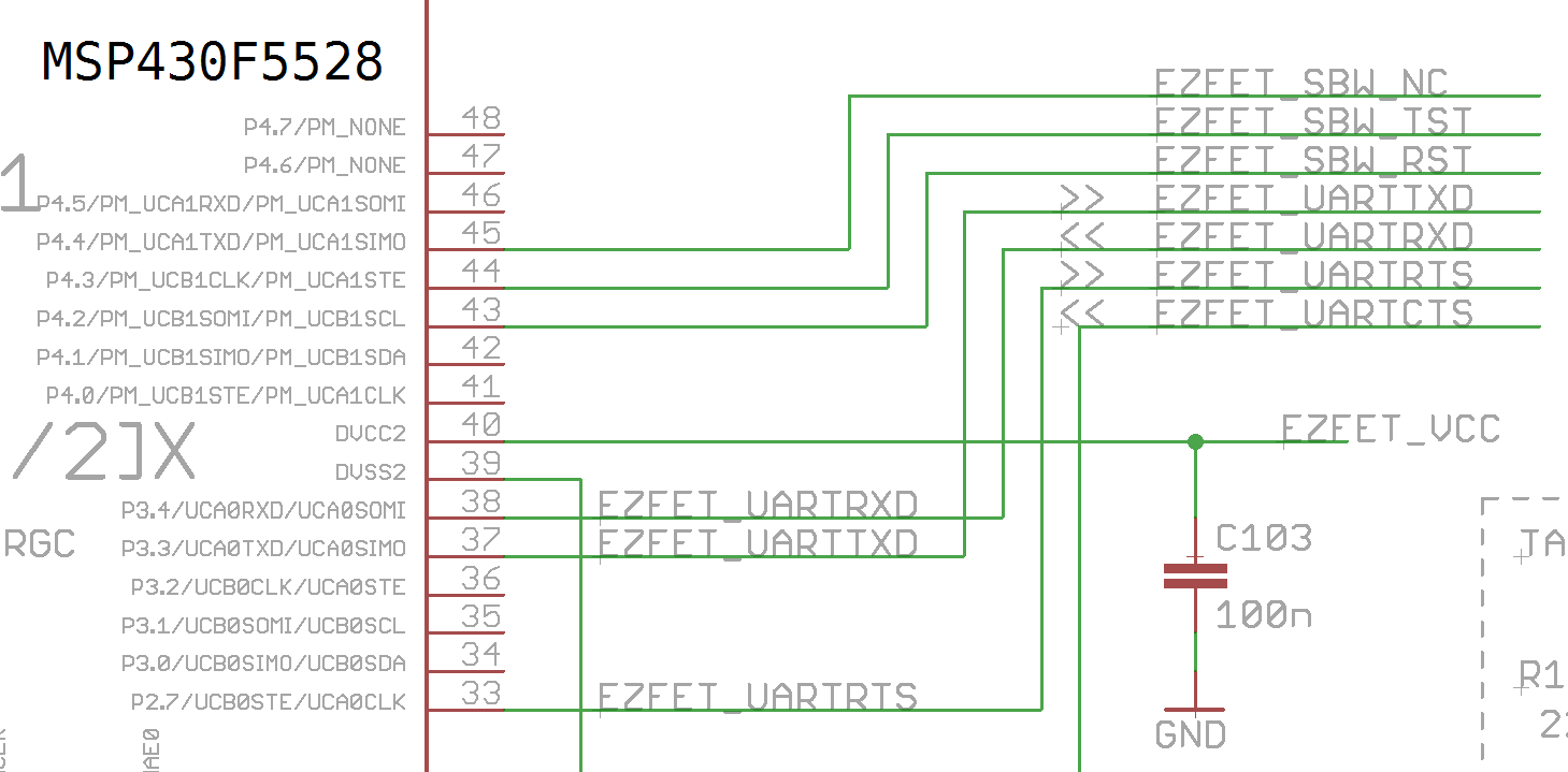
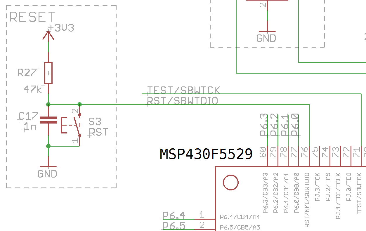
The MSP430F5528 can act as an "ezFET" by interpreting commands arriving via the USB interface to program the MSP430F5529 using the "SPI-By-Wire" interface on the 5529. The 5528 uses P4.2 (pin 43, net EZFET_SBW_RST) and P4.3 (pin 44, net EZFET_SBW_TST) which is remapped through a set of jumpers on the LaunchPad board as EZFET_SBW_RST=RST/SBWTDIO and EZFET_SBW_TST=TEST/SBWTCK. SBWTDIO connects to the 5529 on pin 76, SBWTCK on pin 71.
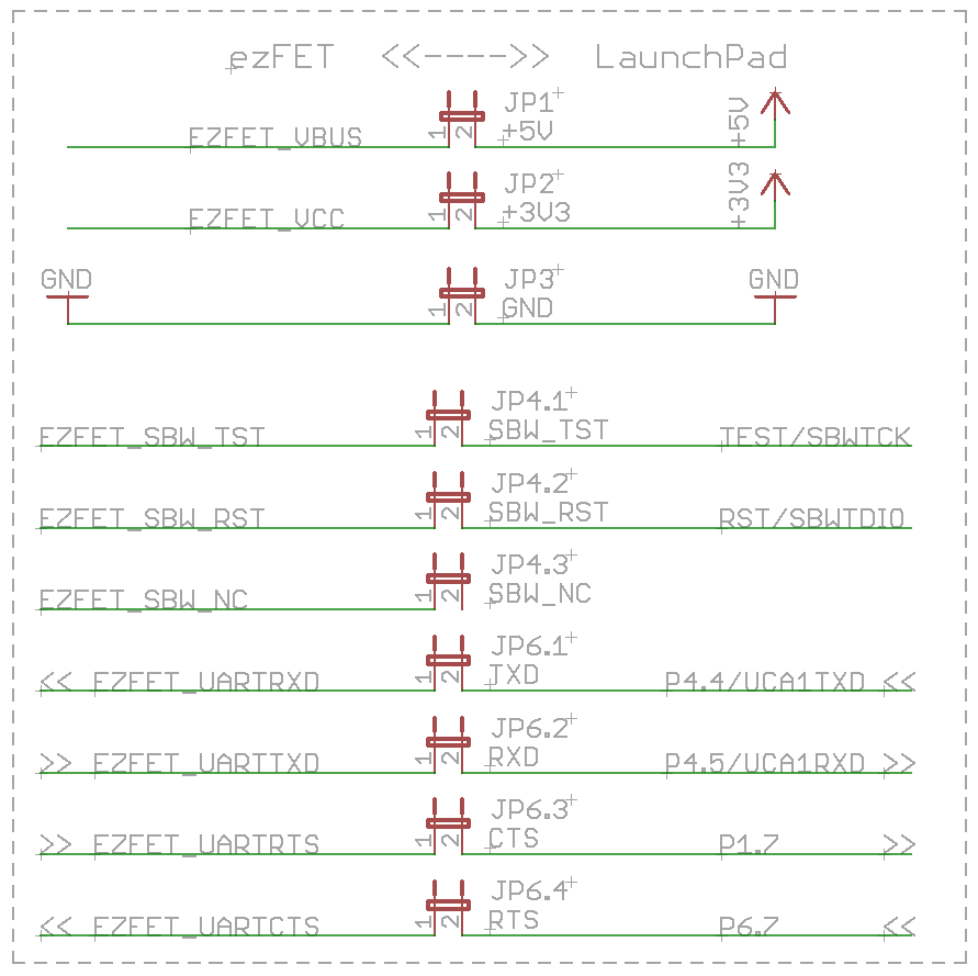
I will be omitting the jumpers.
| 5528 | NET | 5529 |
|---|---|---|
| P4.2:43 | SBWTCK | SBWTCK:71 |
| P4.3:44 | SBWDIO | SBWTDIO:76 |
| P3.3:37 | UARTTXD=UCA1RXD | P4.5:52 |
| P3.4:38 | UARTRXD=UCA1TXD | P4.4:51 |
| P2.7:33 | UARTRTS=CTS | P1.7:28 |
| P2.6:32 | UARTCTS=RTS | P6.7:4 |
April 24 2016
The condensed circuit around the ezFET MSP430F5528. I left a bit of space around the unused pins for future expansion.