
April 3 2016
The Control schematic will include the MSP430F5529 and its
supporting passive components. The first step is to create the
MSP430F5529 component. I created a new component library and
saved it as
S:\Src\HQ\Dev\SB\Chip\EZ430\USB\Work\Control\Brd\CtrlMtr.eli
As I borrow components from JumpMtr02, I need to first copy the components and patterns to the reference libraries in the EZ430 directory, then copy them from there into the CtrlMtr project.
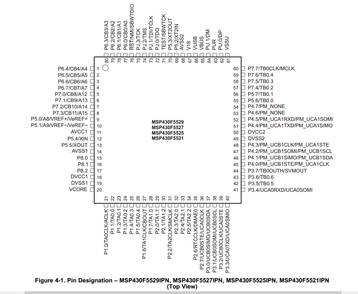
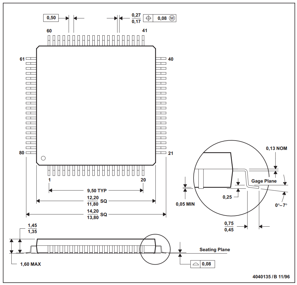
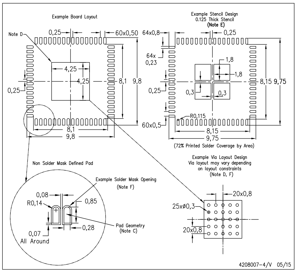
The first component is the MSP430F5529. I need to be careful to follow my naming conventions, so the RefDes is not a simple "U1" but instead "U-MSP430F5529" with a value of "LQFP80". This pays off later during production when "LQFP80" tells me which PnP component to use. I open the MSP430F5529 datasheet and look up the pin diagram and land pattern.

I first create the pins in the Component Editor by selecting
Menu > Objects > Precise Pin Placement...
This opens the "Place Pins" dialog. This drawing will only be used for
the schematic and has nothing to do with the physical location of the
pins on the device, so use dimensions that provide the best
readability. For example, this device has a rectangular array of 80
pins. I offset the top and left by (80/4)/2 * 2.54 to center the pins
on the origin. 80 is the number of pins, 4 is the number of sides, 2
halves, 2.54 is the pin spacing. This creates my rectangular pin
array.
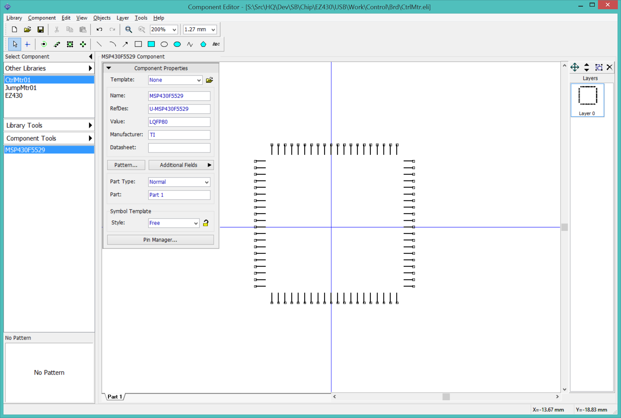
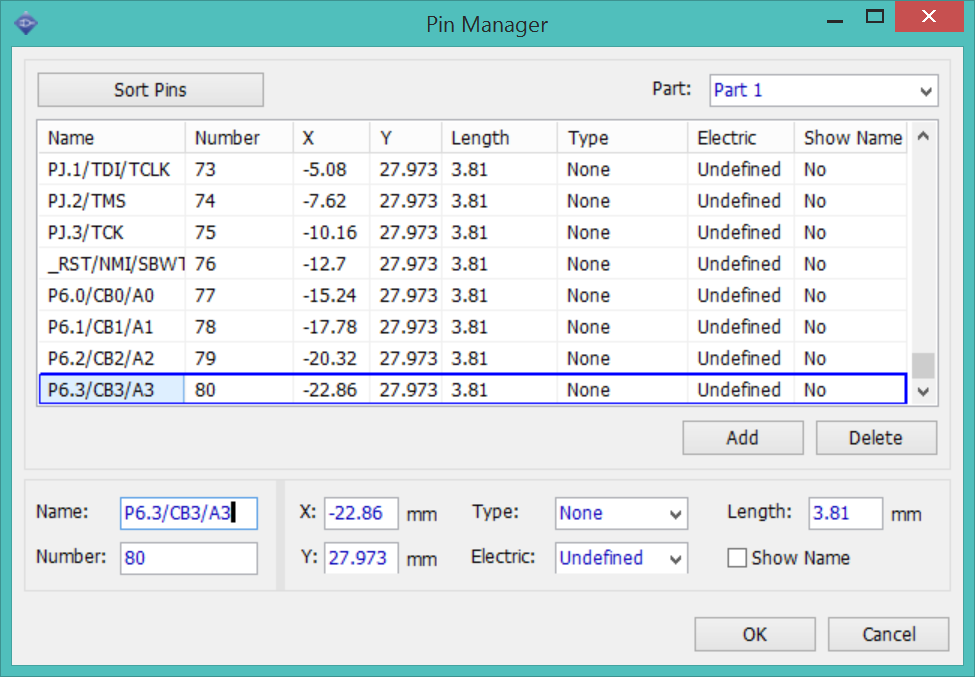
I open the "Pin Manager..." to assign the pins. This is a tedious but necessary step to avoid confusion later. Entering the pin names is quick. Start by selecting pin 1, tab to the "Name:" edit box and enter the pin name "P6.4/CB4/A4", hit the down arrow to advance to pin 2, and repeat for all 80 pins. This goes even faster if someone reads off the pins names. Don't worry about anything other than the names for now. It took me about 10 minutes to enter 80 pins.
I add some shapes and text to make the component easily recognizable in the schematic.
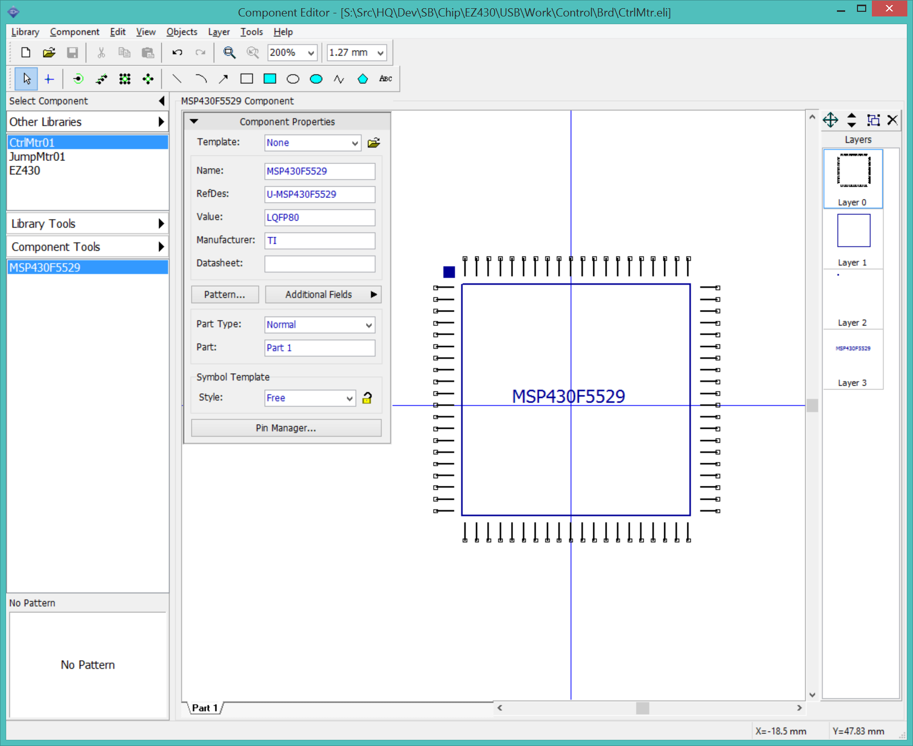
I can create the associated layout pattern for the component now, or wait until the schematic is complete and I am ready to begin working on the layout. There is a fair chance a component might be replaced by a variant or the design might change entirely before that happens, and any time spent working on the pattern now will have been wasted. It is better to defer working on the pattern until the schematic is complete.
So the MSP430F5529, the most complex component in the project, is done in about 10 minutes.
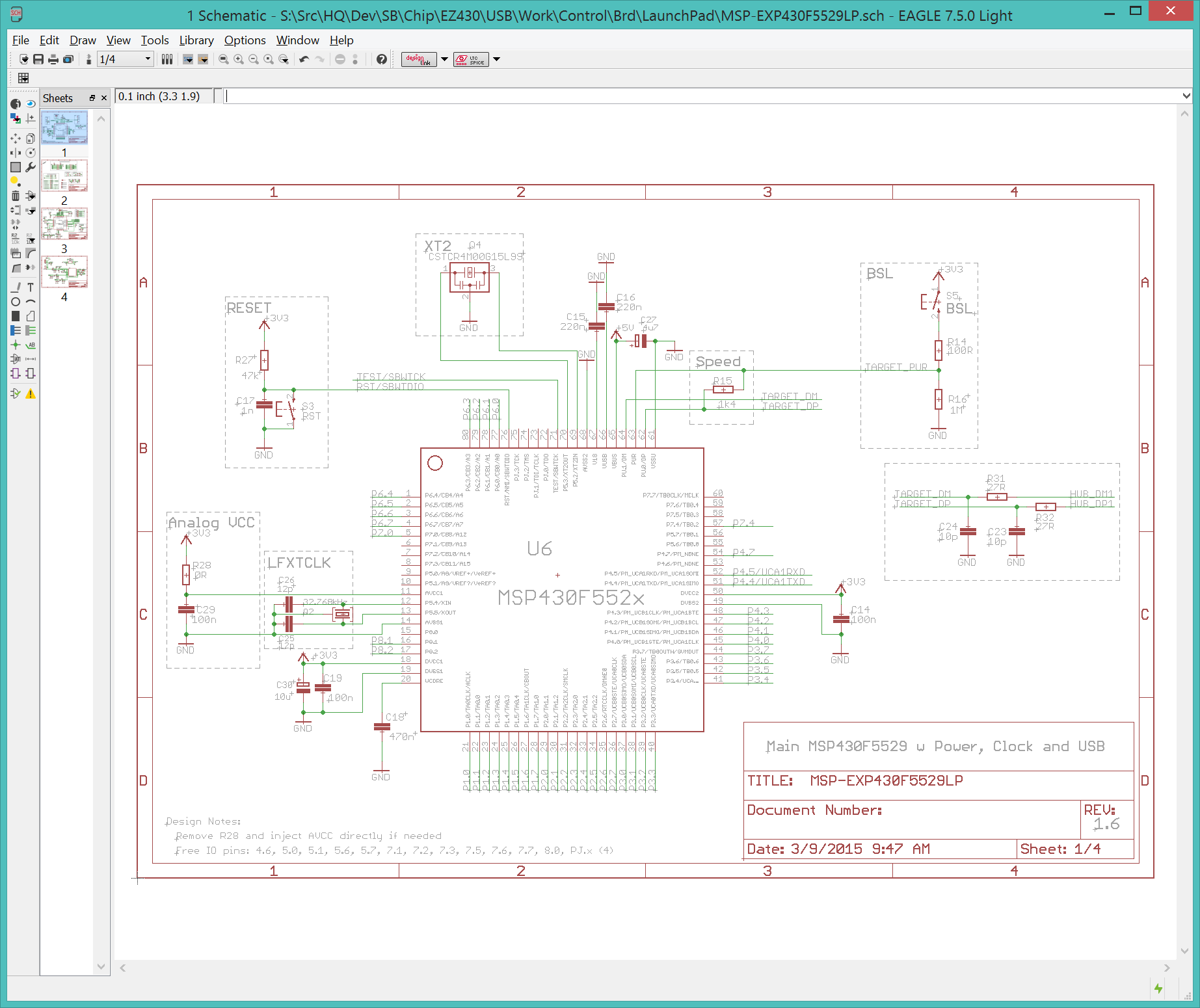
I create a new DipTrace schematic and save it as "CtrlMtr.dch", rename "Sheet1" to "Control", and replicate the MSP-EXP430F5529LP sheet of the LaunchPad reference design.
I place an instance of the MSP430F5529
Menu > Objects > Place Component...
I need to add my new component library. Click "Library Setup...",
select "Project Libraries", click "Add Library", navigate to
"CtrlMtr.eli" and click "Open". "CtrlMtr" should now appear in
the Libraries list. Select it and MSP430F5529 should appear in
the Components list. Select MSP430F5529 and click "Place".
Since this is the focus of the page, place the component on the
origin, then hit Escape to cancel placing more instances.
Apr 4 2016
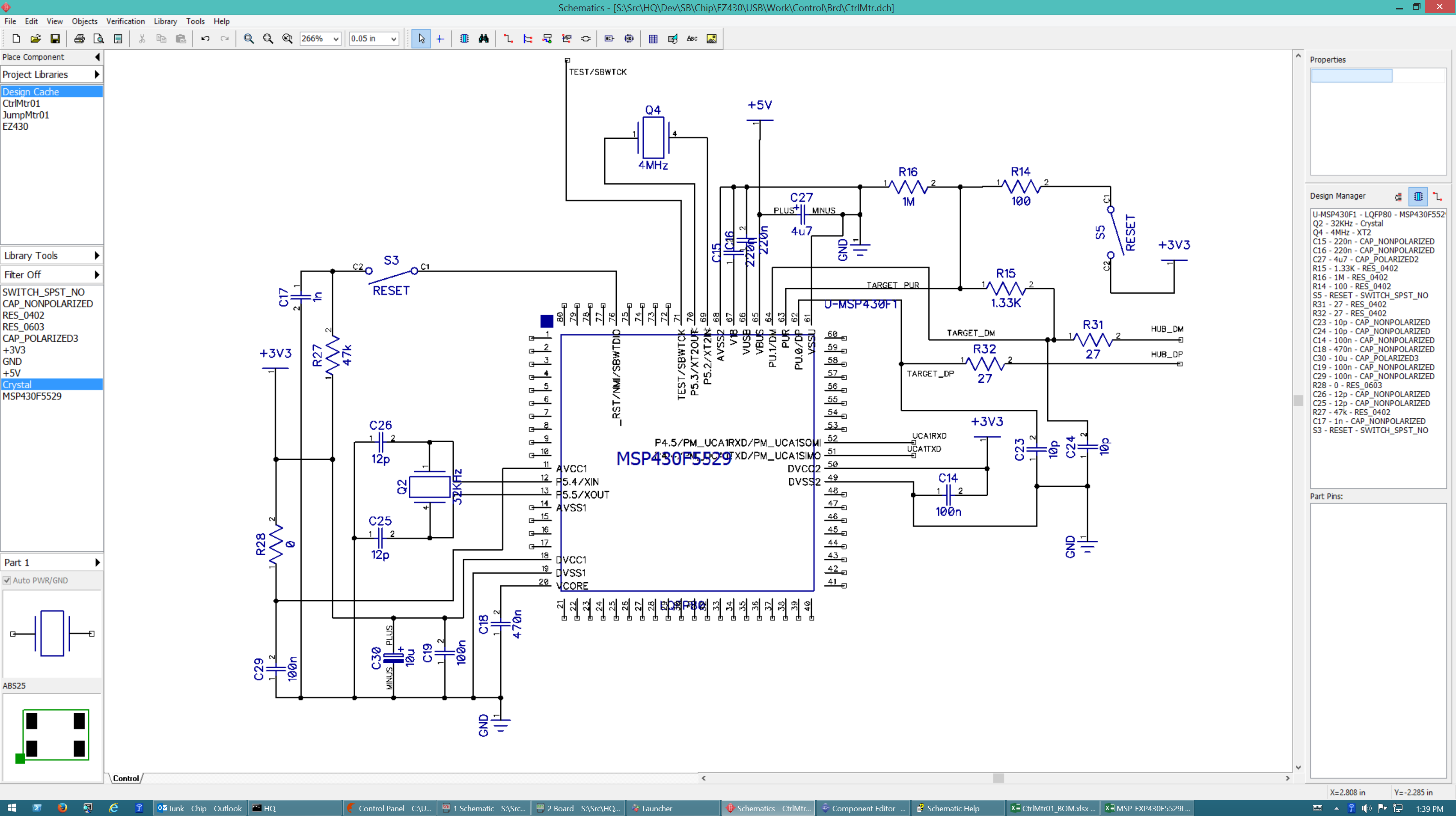
I am filling out the Control schematic, copying from the LaunchPad reference. I am paying more attention to the details of each part.
Each time I place a component, I create an entry in the Parts sheet of my BOM. I look for the component in the BOM sheet. If it already exists, I add the RefDes to the entry on the BOM and enter the PartID in the Parts sheet.
If the component is not in the BOM, I need to create a new part entry. The LaunchPad BOM has all the information, including a Digikey stock ID, that I need.
C27 "CAP TANT 4.7UF 10V 10% 1206, Digikey 493-4142-1-ND" is not a valid Digikey stock number, replacing with 718-1146-2-ND.
C18 "CAP CER 470nF 16V 10% X5R 0402" is expensive, $160/10000. Look for a cheaper alternative.
C30 "CAP TANT 10uF 10V 20% 1206, Digikey 493-2351-1-ND" is not a valid Digikey stock number, replacing with Samsung 1276-1853-2-ND.
What is the difference between a ceramic and tantalum capacitor?
Part35 CAP CER 12pF 0402. The reel is 50,000 parts. Look for a replacement in smaller quantity.
I completed transcribing the Control schematic after about 3 hours. I added a new column to the BOM: "StartUp". This is the cost for stocking a new reel of a part that has a very small per-unit cost but can only be bought in large quantities. Items like 0402 caps and resistors. The BOM fills up fast, I will need to do some research on replacing some of the pricier items.
| Signal | 5529 | 5528 | TC2050 |
|---|---|---|---|
| TDO | 72 | ? | 1 |
| Vcc(Tool) | 50 | ? | 2* |
| TDI | 73 | ? | 3 |
| Vcc(Ext) | 50 | ? | 4* |
| TMS | 74 | ? | 5 |
| -- | -- | -- | 6 |
| TCK | 73 | ? | 7 |
| TEST | 71 | ? | 8 |
| GND | 49 | ? | 9 |
| /RST | 76 | ? | 10 |
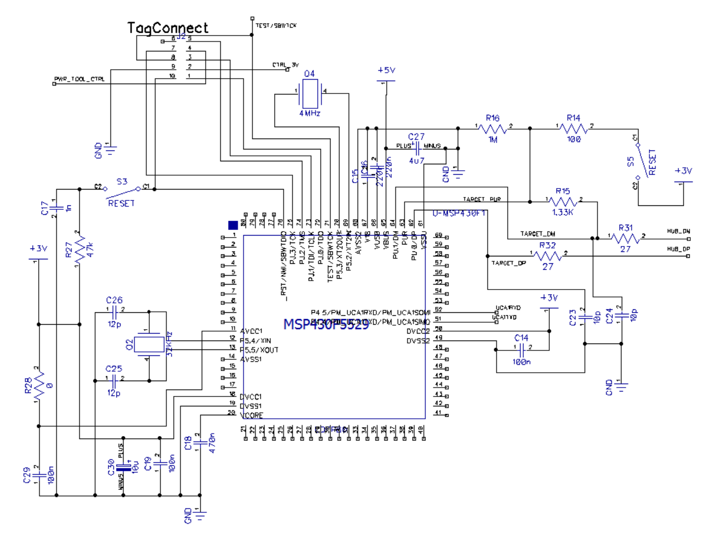
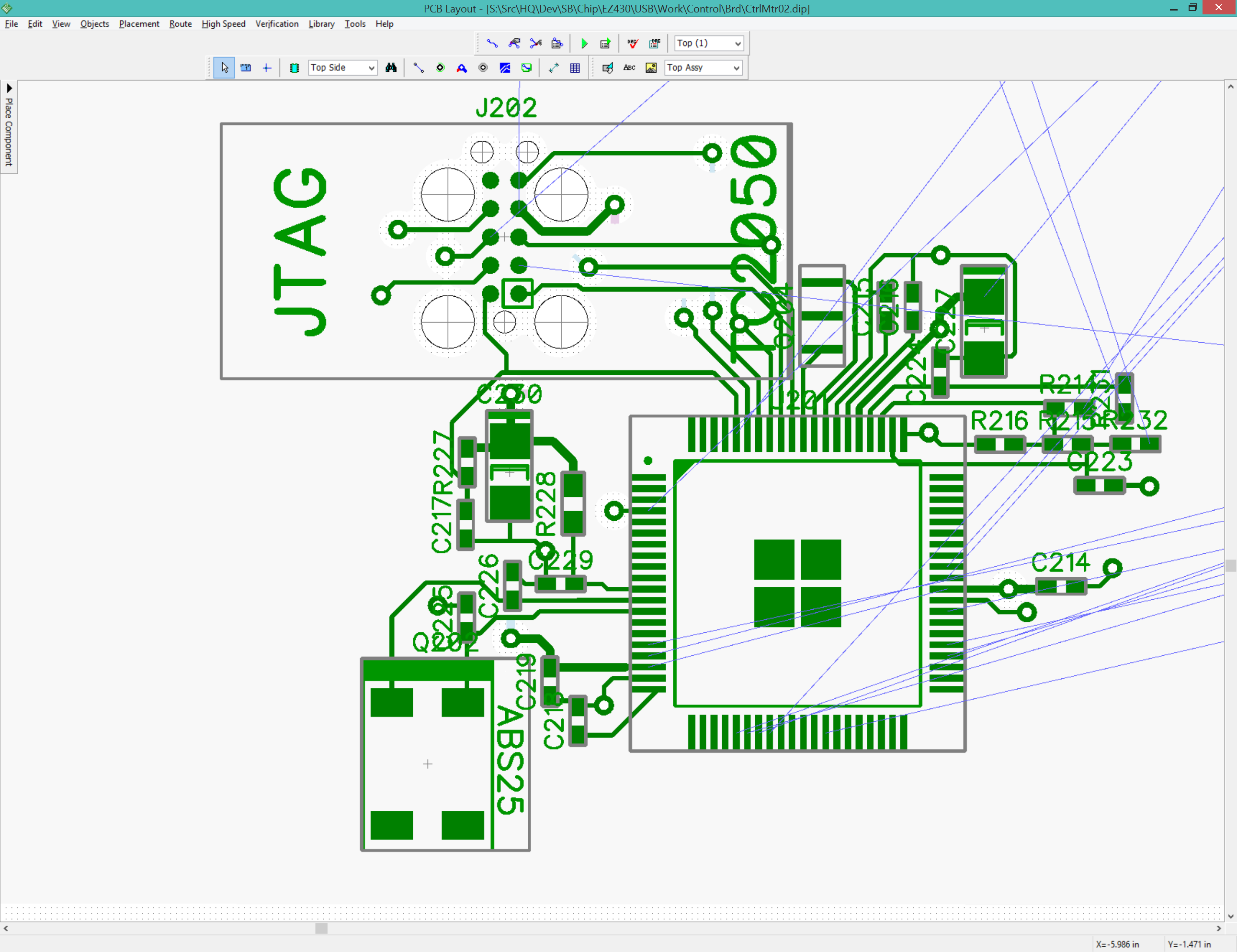
The first generation of this board needs a direct JTAG connection to both the 5528 and 5529 in case the ezFET circuit fails for some reason. I can remove the JTAG connection to the 5529 once the ezFET is proven to work. I will be using a TagConnect (See Tag-Connect) interface to save space and the remove need to add header pins. I copied the TC2050 component from the EZ430 component library. The table below shows the connections from both the MSP430F5528 and MSP430F5529 to the TC2050 connector.
The external programmer can provide power to the target device during programming, which can be very helpful. However, this requires some way to select which power rail is connected to the target device, shorting Vcc(Tool) and Vcc(Ext) can damage the programming tool. The easiest method is to use three header pins arranged TOOL-MSP-EXT and use a jumper to tie MSP (which leads to the MSP Vcc pin) to either TOOL or EXT power. The power selection logic became complicated enough to warrant its own schematic sheet, "PwrSel".
The Control schematic with the TagConnect interface.
April 24 2016
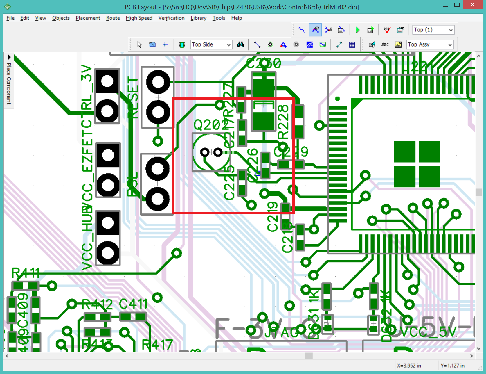
The condensed MSP430F5529 main control circuit. I left plenty of space around the unused pins for future expansion.
April 27 2016
The SMT 32KHz crystal is no longer in stock. I am replacing it with the through-hole version at roughly 1/10th the cost. AB38T-32.768KHZ (Digikey 535-9034-ND).
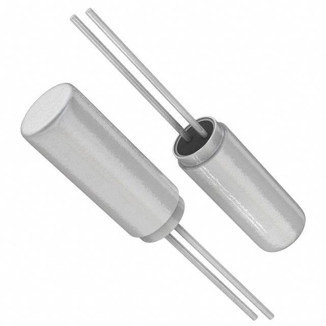
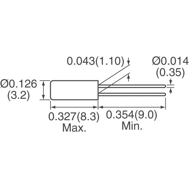
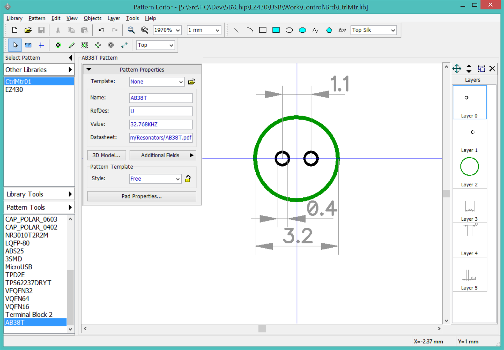
There is room to fold the crystal over to lay flat on the board.