
Dec 24 2015
The connectors for the cable between the Overo and Caspa are tiny, delicate, and wear out after a very limited number of insertion cycles. The Overo connector will not survive very long if that big Caspa board is allowed to flop around on the end of the semi-rigid ribbon cable. This also applies to the WiFi antenna. So before even thinking about connecting the Caspa board, I need to create a rigid test fixture to hold the boards in place and remove excessive strain on the Overo connectors.
Bruce designed a high-speed serial link between the camera and the overo for BLIS. He was quite pleased with the performance and simplicity of the arrangement. Eventually, I might want to look at that to see if I could move the video signal onto a flexible round cable instead of a semi-rigid ribbon cable, if the camera is mounted to a motorized gimbal.
The ribbon connector exposes the conductors on opposite sides at each end. The cable needs to be inserted into the connectors with the exposed conductors faced toward the board (down), which means something needs to flip.
The Caspa needs to be in one of two orientations: to the side and facing down (with respect to the Overo), or above the Overo and facing up.
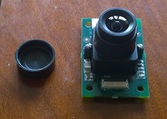
The figure on the left shows the "lens down" orientation, looking down at the Overo. The figure on the right shows the "lens up" orientation, looking at the edge of the Overo with the Caspa hovering above it and facing up. Both have advantages and disadvantages.
The fixture for "lens down" would be the easiest to fabricate and provide the best access to the microSD and peripheral ports. There would be some interference with the HDMI port, but it would still be usable. Having the lens facing down might make it awkward to frame the image. This fixture could be made easily from a single flat plate, using risers to secure the boards. The lens would extend through a hole in the plate. The fixture would need legs on the bottom to protect the lens.
The "lens up" fixture is more complicated as it would need to have a second plate for the Caspa supported above the Overo base plate. This fixture would have no interference with the peripheral ports and the lens would be looking up from the workbench.
A third option is a hybrid "lens out" orientation, mounting the Caspa plate perpendicular to the Overo base plate. There would still be manageable interference with the HDMI port. The lens would now be looking horizontally out from the base plate, which would be ideal for both the workbench and mounting into a vehicle chassis. Further, the Caspa plate could be mounted to the base plate with a hinge to allow the Caspa to tilt up and down. Mounting the base plate onto a turntable would allow panning left and right, providing full pan-and-tilt range of motion. The strain on the connectors could be minimized by rigidly securing the cable to both plates. This fixture is only slightly more complex than "lens up". This seems to be the right design, provided it isn't too complicated.

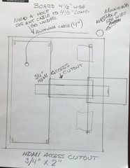
These are my first (very) rough sketches for the fixture. First is the base plate for the Tobi board. In addition to anchoring the Tobi, it needs to also provide a mounting hole for the WiFi antenna, provide access to the HDMI port under the Caspa cable, and provide space to anchor the pivot axle for the Caspa board. The Caspa cable is only 80mm long, make sure the axle is placed the appropriate distance from the Overo. It needs to not stretch or crimp the cable.

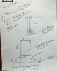
The Caspa plate's primary purpose is to provide a fixture for the hinge axle. It needs to provide a way to adjust the friction on the axle from free-spinning to rigid. I know that if I design the hinge exactly, it will be either too loose or won't fit. The best design for a prototype is to make it adjustable. I settled on a simple plate with four mounting holes and a half-pipe channel for the axle. The axle will lift the plate from the Caspa board by the difference between the depth of the channel and the diameter of the axle. The depth of the channel can be made shallow to increase the clamping pressure, or deep to minimize the gap. The friction on the axle can be adjust by tightening or loosening the nuts on the two mounting screws closest to the axle.

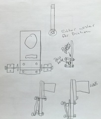
The hinge between the base and Caspa plates is made by running a 3" pin through two risers on the base plate and the clamp on the Caspa plate. For a rigid configuration, a locking nut can be added to bind the axle to one of the risers and prevent it from spinning. The locking nut can be omitted to allow the axle to spin freely. The height of the risers can be adjusted to move the camera above the base plate.
This is an intentionally simple design to get things rolling.
The only components that are not flat plates are the two risers, which are simple cubes (or rectangular boxes) with 3 holes. These can be fashioned from plastic, wood, or anything that is readily available.
I am contemplating fashioning the plates from PCB board. It is quick and easy to design the PCB using DipTrace and have Bay Area Circuits cut the boards. Eventually, the base plate will hold the MSP430 and motor driver components and I can then design the circuit directly into the base plate.
Choosing the dimensions of the axle turns out to the be linchpin to the entire design. The diameter of the axle can't be more than half the thickness of a blank PCB. The diameter of the axle determines the diameter of both the axle head and locking nuts, which determines the minimum height of the risers.
An alternative to a single long axle would be two small pins that extend out from either side of the clamp into receiving sockets on the risers. A center cutout would allow me to retract the pins while positioning the Caspa, slide the pins out into the riser sockets, then tighten the clamping screws. The length of the pins would be limited to half the width of the Caspa, and the extension distance would be limited to half the width of the cutout. The width of the cutout would be limited to the width of the Caspa board less twice the width of the clamping legs. The clamping legs should be a wide as possible and no less than 1/4".
If these pins are smooth rods, there will be no way to prevent them from rotating in the risers with adding a clamp (or set screw) to at least one of the risers.
A variation on this theme: Instead of two clamping plates on the Caspa, use a single plate and glue two 1/4" plastic risers to it. Drill a through-hole for the axle. Use 2 1/8" shoulder screws to tranverse the base and Caspa risers on each side. One side is allowed some free play, the other can be tightened to bind the Caspa riser to the base riser to hold the Caspa board in place. It may be difficult to make the through-holes line up, for all four of the risers, the holes need to be drilled accurately and they need to be placed and glued accurately. However, the fit is not critical so I could compensate by oversizing the holes.
This design requires two 7/8" x 1/8" 4-40 shoulder screws. Standard sizes seem to max out at 1/2" length. I have more choices if I use 6-32 thread, with 3/4" length as a standard part. Going to 8-32 thread with a 3/16" diameter lets me go to 1.5". RAF Electronic Hardware seems like a good source.
I could try to cut the plates on my mill, if it works I could then use any material. My question: How do I secure a plate on the mill to cut it. I would assume I would clamp it to a sacrificial plate and chew it up as little as possible.
OnlineMetals has 12x12" 1/4" MIC-6 aluminum plate for $51.57. US Plastics has 1/4" vinyl sheets in various sizes, 48x48x1/4" is $98.65, 24x48x1/4 is $48.44, 24x48x1/8" is $24.22, and 24x48x3/16" is $36.34. I would need to chop it up into usable pieces on the table saw. The aluminum would let me tap bolt holes directly into the plate, but it might be hard on my mills. The vinyl would be easier to cut to size and is about 1/10th the cost of aluminum but would require the working piece to be clamped to the table.
The vinyl might be usable for the Base and Caspa plates as well.
A day spent fiddling with the mechanical design (Mechanical) has reinforced that the base plates should be PCB. Eventually the Tobi board will be removed from the design and its equivalent electronice embedded directly into the base plate.