Friday May 8 2014
The first BlinkMtr01 board built OK, but the MSP430 failed to connect. The programmer complained about an invalid voltage reading. I am assuming that the driver IC is mismatched on the voltage level and is pulling the VCC too low. So I need to build a second board with just the MSP430 parts to test the JTAG connector.
The MSP430-only parts are:
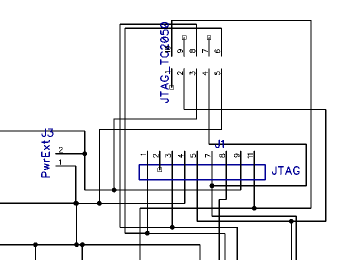
Well, that did not work either. Reviewing the schematic I find the problem: I used the wrong Vcc pin on the JTAG14 connector. I connected Vcc/Ext instead of Vcc/Tool. Oops.
I believe the PowerExt is connected correctly, so I solder a 2-pin header in place and connect my lab power supply at 3.4V/0.25A. Still no signs of life. :(
It is strange that I don't at least see the green power LED (D3) light up. It is connected directly to power and ground. After examining it under the microscope and comparing it to my KGR Blinky01, I discover that D3 has been placed backwards (again!).
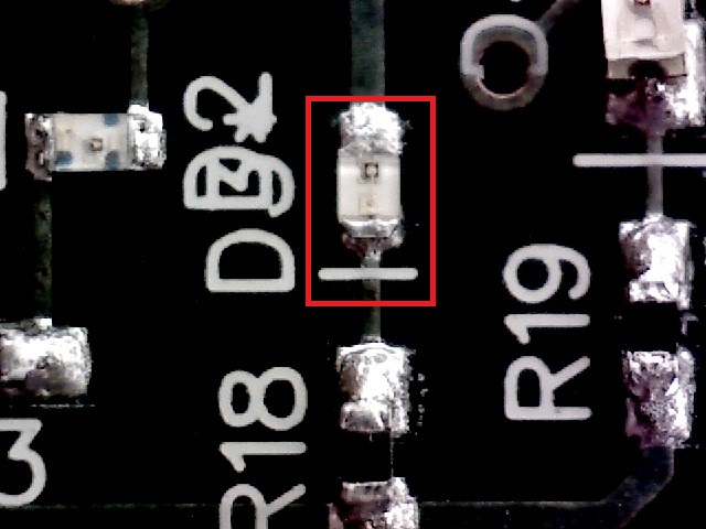
Note that the black square/star pad on the LED is not on the
diode bar side!
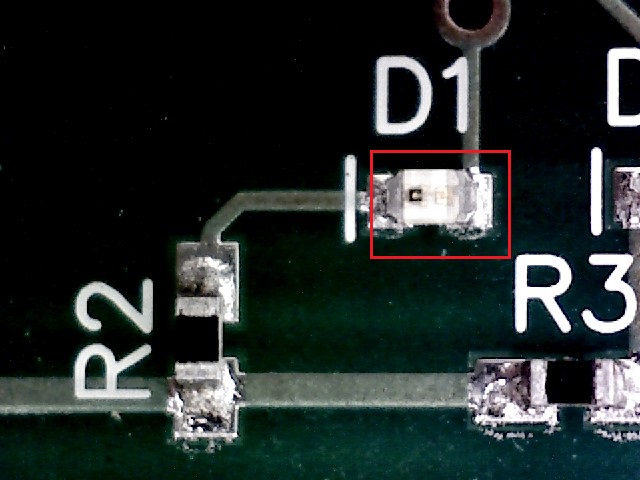
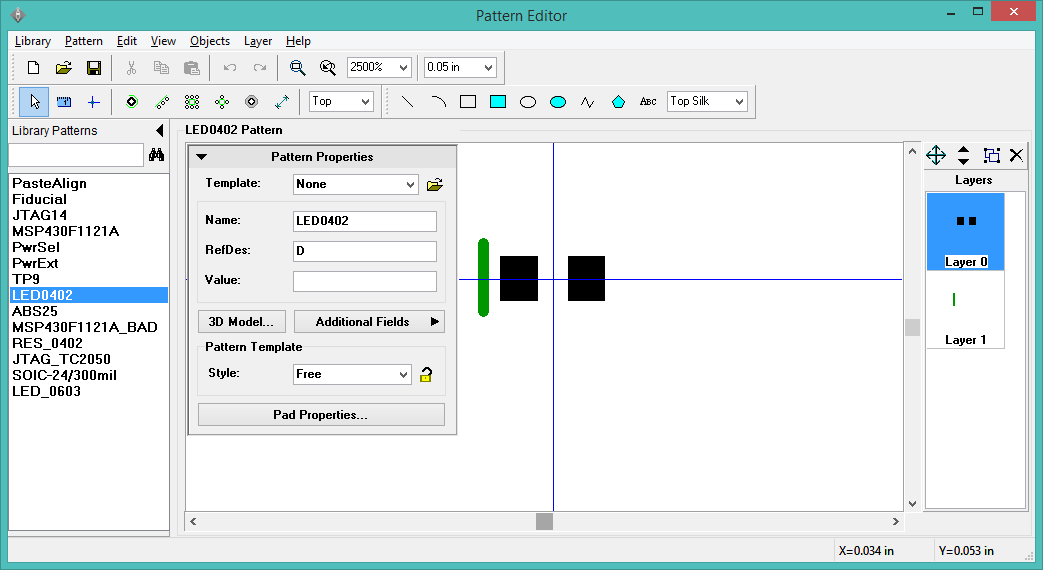
This is a correctly placed Rohm 0402 LED. The cathode (ground) is the
star-shaped pad with the black square. On the schematic and silkscreen,
the diode bar is on the ground side.
How do I make sure I don't make this mistake again? This is the part specification from the Rohm datasheet (sml-p11_p-eco.pdf):
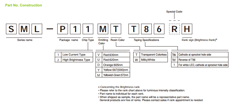
The label on the part reel reads "SML-P11MTT86", which translates to low current, yellow/green, transparent, cathode at sprocket hole side. The sprocket is on the left.
The component pattern also has the cathode on the left, so this should be a pick angle of 0 (normal).
Unfortunately, I somehow decided the pick angle should be 180. This is wrong. It should be 0 (Normal).
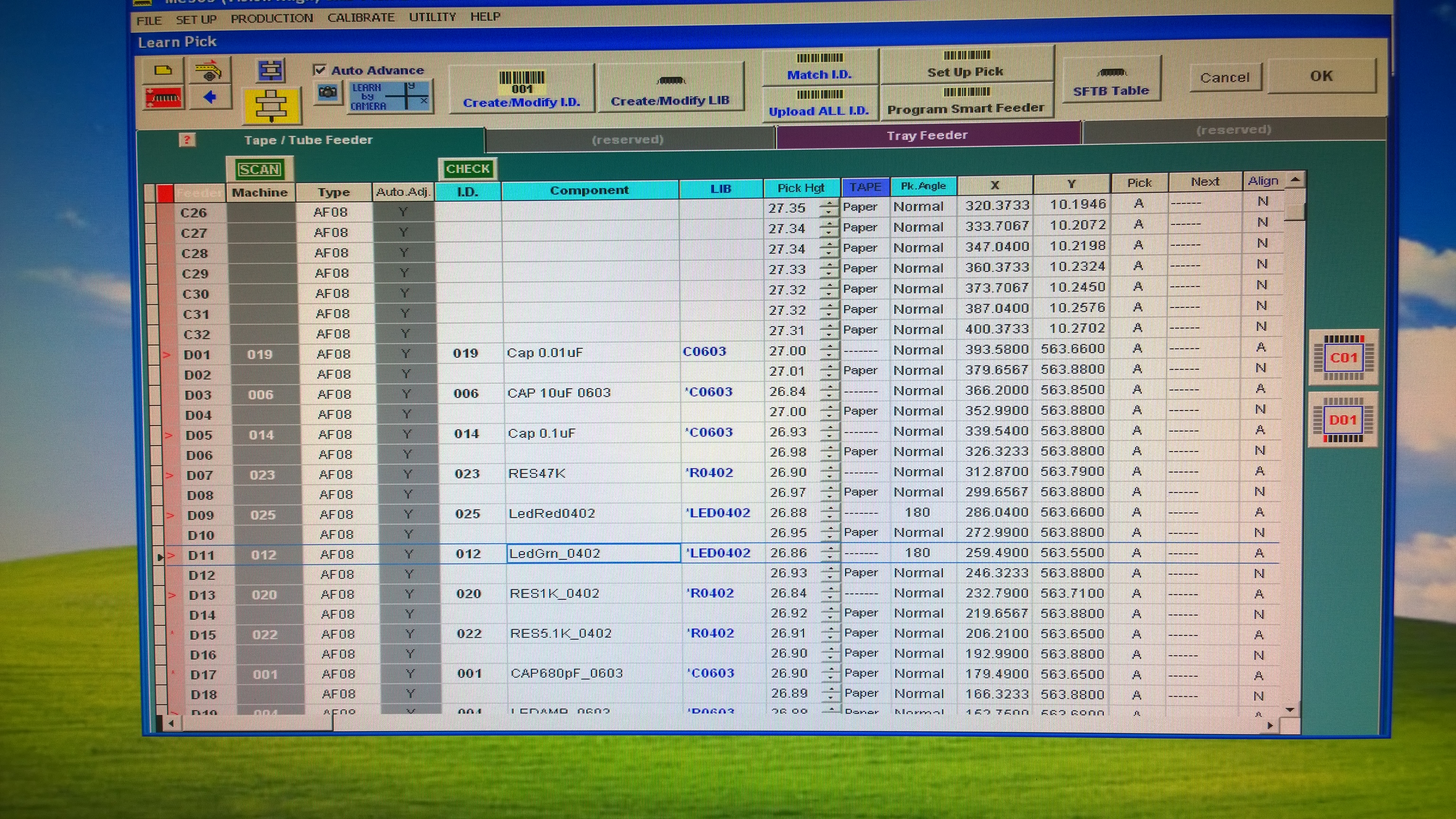
This is corrected in the "Setup > Learn Feeder ID" dialog. Both the red and green LEDs need to be changed to "Normal". It must also be updated in the "Learn Pick" window.
I toss another $20 in the garbage and build another board... I am expecting to at least see the green power LED light up when I apply power to the PowerExt pins.
Another practical lesson: It is easier to deal with solid copper wires soldered into the PowerExt holes than the 2-pin header.
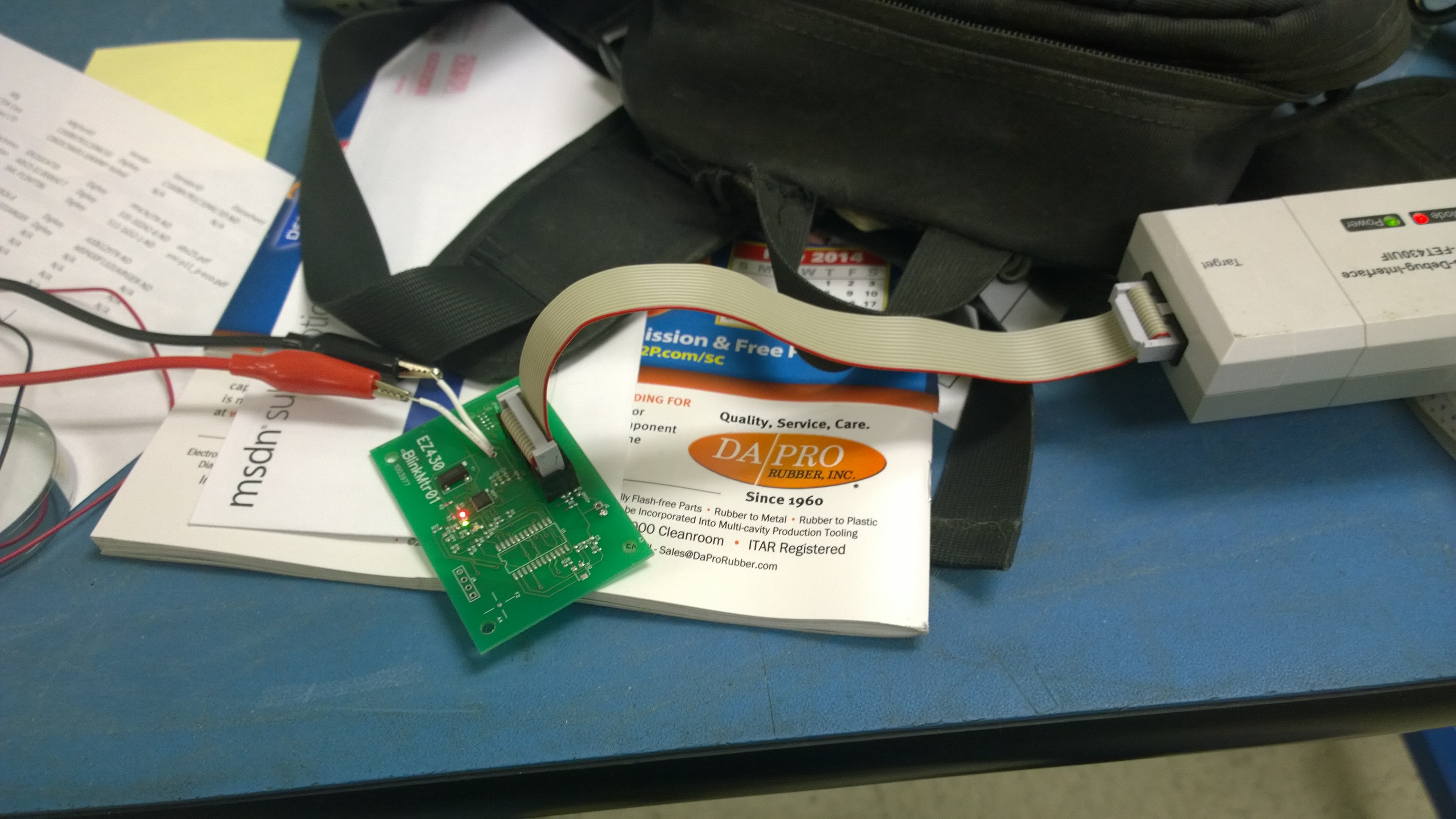
Success! At least the power led lights up....
Success! With external power, I am able to program BlinkMtr01!
I still have 3 more boards left, so I go for broke and build a fully populated board... The assembly has now become almost routine.
Success! I am able to program the fully populated board!
Fail! However, the Tag-Connect does not work. "Unknown device." The JTAG14 connector works, so I will leave the TC2050 for later.