dev.nlited.com

>>

Schematic

<<<< prev
next >>>>

2014-07-21 21:26:42 chip Page 1088 📢 PUBLIC

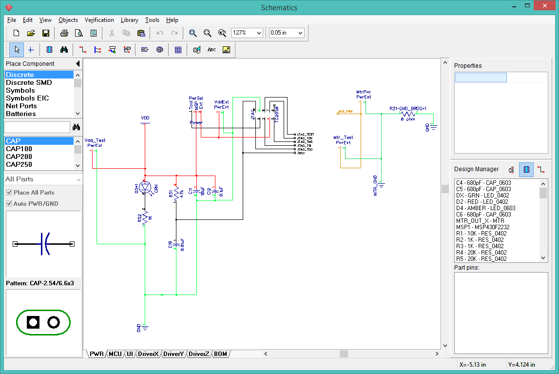
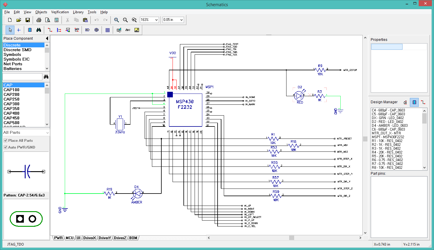
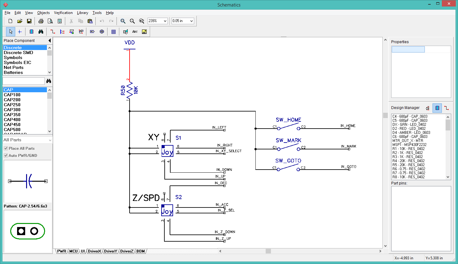
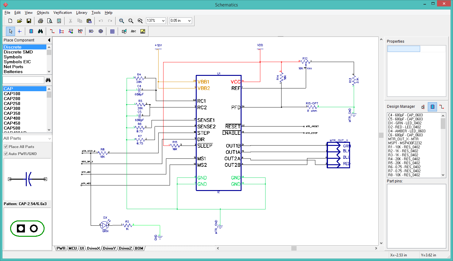
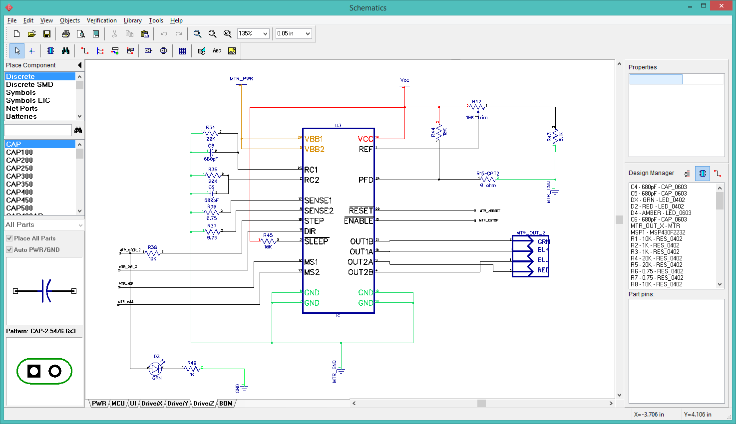
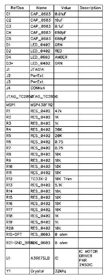
I spent some time cleaning up the BlinkMtr03 schematic, trying to remove redundant resistors and organizing the functional blocks. It is clearly a good idea to keep the number of components on each schematic sheet to a minimum. I split the design into six sheets:

PWR: The power input pins, power indicator LED, the filter caps, the JTAG header, and the motor power input pins. BlinkMtr04 will include a DC/DC power converter to step PWR_MTR down to 3.3V so I can use a single power source.
MCU: The MSP430, crystal, MTR_RESET led, and MTR_ESTOP led. Everything else on this sheet is just connectors from the MSP430 pin to a net name somewhere else.
UI: The joysticks and pushbuttons.
DriverX, DriverY, DriverZ: These three sheets are duplicates, with the only difference being the input and output net names.

The only problem I see at the moment is that MTR_RESET and MTR_ESTOP signals are active LOW. The leds are currently hooked directly to the signal lines, meaning they will be lit when the signal is NOT TRUE. I will deal with that later.

I upgraded to DipTrace 2.4.0.2.

BlinkMtr03 schematic power
Power Circuit

BlinkMtr03 schematic MCU circuit
MCU Circuit

BlinkMtr03 schematic UI circuit.
UI Circuit

BlinkMtr03 schematic X-axis motor driver circuit.
Driver X-axis

BlinkMtr03 schematic Y-axis motor driver circuit.
Driver Y-axis

BlinkMtr03 schematic Z-axis motor driver circuit.
Driver Z-axis

BlinkMtr03 schematic BOM
BOM


WebV7 (C)2018 nlited | Rendered by tikope in 98.868ms | 18.117.104.63