Saturday May 31 2014
The boards arrived on Thursday May 22 and I went to the office for the first build on Friday. This turned out to be a complete disaster for several unrelated reasons. First, I made the mistake of bringing Kaspar and Misha along to the office. Misha began whining to go outside almost immmediately and was a constant distraction all day long. And Digikey had mispicked the A3967 parts. The parts bag had two labels on it, A3967 motor driver (correct order, incorrect contents) and FTDI serial driver (incorrect order, correct contents). In my haste to finish before Misha exploded I started grabbing parts without looking at them. First I tried to place an MSP430 TSOP, then the FTDI TSOP where the A3967 should go. When I finally took a breath and discovered the labeling error I found I had no more A3967's remaining. I placed everything except the A3967 on a board, but by this time both Misha and Kaspar were becoming very anxious and upset. So I grabbed the board and took it home without and testing in the lab.
On Saturday I tried to test the board, but without the JTAG14, PowerSel, and PowerExt headers it was difficult. I used a paper clip to short the PowerSel pins and connected the TagConnect but there were no signs of life. Since the Vcc LED did not light up, this was an inconclusive test.
It is now Saturday May 31. Digikey corrected the A3967 order and I now have 20 in stock. I will finish the first board by adding the headers, then test the TagConnect/JTAG14 connections. Then I will build a second board with an A3967. The second board, assuming it works, will be used for load testing. I want to see how fast I can turn the motor, how much power it consumes, how much heat it generates, and how well the heat is dissipated.
=====
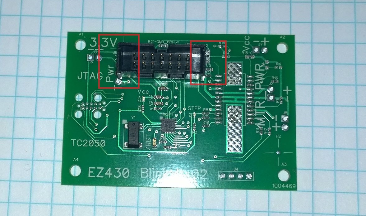
PROBLEM: I did not make enough space around the JTAG14 header! The header interferes with R12 (the 10K trim pot), C5, R5, and the Pwr header. I can work around these problems, but I need to go back to the JTAG14 pattern and make the silk outline match the actual physical size of the header to avoid this problem in the future. The dimensions are 25x9mm.
The board is still dead after adding the JTAG14 header and a jumper to select Pwr/Tool. The Vcc LED is dark but it will light if I touch the scope probe to the cathode. I confirmed that the LED is placed correctly (dark star to the annode/ground side). CodeComposer is unable to identify the MSP430 part number. This is very frustrating, since I do not know why the board is failing. Is it a design error, placement error, assembly short, or bad part? I cannot move forward until I prove that the MSP430 side of the board is OK. This means the next board will need to be an MSP430-only board; a new intermediate step.
The parts list for an MSP430-only build:
C1 C2 C3
D2 D3 D4
MSP1 Y1
R1 R3 R18 R19
11:22 Starting the MSP430-only build. I left a bit of a mess behind last time. My small solder paste work tub was left open and now contains dried paste, I will need to clean that up first. At least I cleaned the stencil. I cleaned out the tub and refilled it with a dollop of paste from the fridge. I now need to wait 20 minutes or so while the cold paste warms in the incubator.
13:15 MSP430-only board is complete and running. I took some time to update my PnP docs, the actual build probably took only half an hour (including the 20 minute bake time). So now I know my MSP430 circuit still works and the JTAG14 connection is OK. This just shows that when I try to build something in a hurry or when I am distracted it probably won't work.
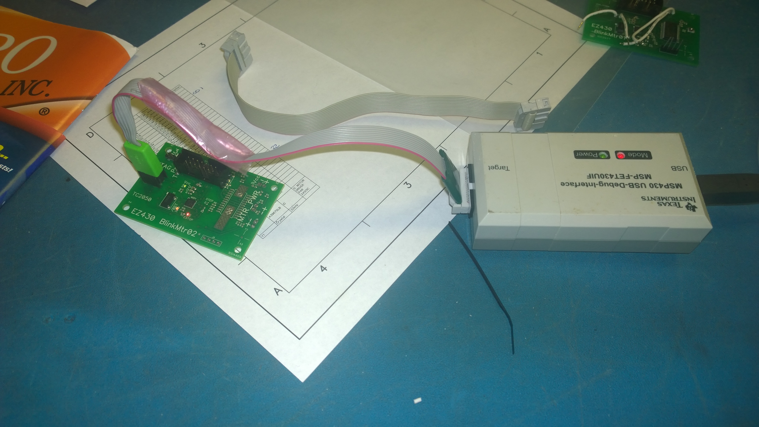
I replaced the JTAG14 with the TagConnect cable and tried to reprogram the device... SUCCESS! I am now able to use the headerless TagConnect cable, saving me the space, parts, and trouble of using the JTAG14 header.
13:25 Now that I am back on track, I can build a fully populated BlinkMtr02 board. I don't need to worry about the interference with the JTAG14 as I will now be using the TagConnect.
13:54 I applied solder, but I was a bit off and the paste placement was marginal. It was good enough to continue and hope it reflowed onto the pads, but there is a fair chance this board won't work. I had to reload the tray components and relearn the pick locations. The parts placement went smoothly, only the A3967 failed. I retrained the component library image and it went down on the next run.
I tried to use the Manncorp oven software to monitor the oven, but it was unable to read the temperature and never started the oven. The oven is still usable, I can read and program the profile from the software but I need to start the oven manually from the green button. There is not a single piece of software associated with these machines that I would consider acceptable for release, the software quality is truly dismal.
14:55 The board came out of the oven and passed the MSP430 blink test, so the solder was OK. I added the power connector headers, but repeated an old mistake: I added a 2-pin header for the motor power inputs instead of soldering wires. I was able to remove the header but I could not get the wire into the hole because it was now filled with solder. So even though I believe the board works, it was easier and faster to set it aside and build a third board. The third board built very smoothly, no placement errors! I am now waiting for it to bake, then I will add the headers and wires and see if I can apply power and spin the motor. NOTE: Make sure the 4-pin motor output header pins have the thick posts that fit into the motor's receptacles.
15:23 Success! BlinkMtr02 is turning its motor! I forgot to label the motor output pins. Now that the TagConnect is working, it is much easier than dealing with the JTAG14 headers.
The heat sink seems to make a big difference. The A3967 is not heating up past about 130F now. I am supplying 8V to the A3967 and it is drawing about 130mA, which seems to be fairly independent of how fast I step the motor.
I need to delay at least 425 cycles between steps. I also need to delay (1000 cycles?) when changing direction.
The motor has been wagging back and forth at about 2 revolutions per second (which seems to be its top speed) for about 20 minutes now. Temperature is holding steady at 130F. I think I can declare victory with BlinkMtr02 and move on to BlinkMtr03. :)